
Of Old Radios And Related Items--Published Monthly
Restoring an RCA Theremin
By Mark McKeown
Web Edition
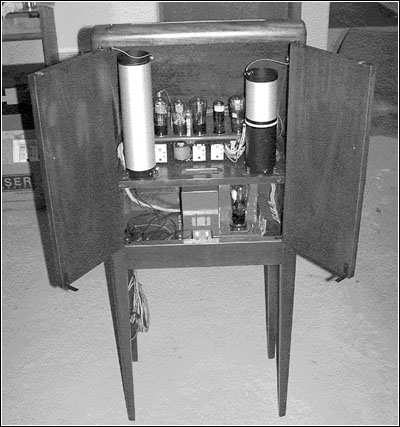
Although not a radio, the Theremin was manufactured by RCA in 1929. It was included in the well-known RCA "Red Books" and was sold by RCA radio dealers. Open the rear doors, and you will see what looks much like a radio chassis, with tubes, transformers, capacitors, etc. However, a couple of unusual items -- tall coils and antennas on the cabinet -- give away the real nature of the Theremin. It is, in fact, a musical instrument.
An October 1990 A.R.C. article by Mark Kitner describes the Theremin generally, but Mark McKeown describes the extensive restoration of a Theremin in this article. Many of the details will be unfamiliar to those who have never seen a Theremin, but all will appreciate Mark's careful work in restoring a radio-like musical instrument. A number of tips will also be useful in radio restoration. (Editor)
The history of the invention of the Theremin by Leon Theremin is well known so I won't go into it again. Suffice it to say, his invention opened up a new world of electronic musical instruments from the Theremin to the Ondes Martenot to the modern synthesizers we see today.
My inspiration probably came from the movie Forbidden Planet, which has some great Theremin-like sounds. My first Theremin, built in the mid-1970s, was a Robert Moog design, published in Radio and Television News in 1954. Parts for tube equipment were hard to find even then, and I had to have two of the TV horizontal sweep coils required in the circuit wound by the original manufacturer. This Theremin ended up in a rock band.
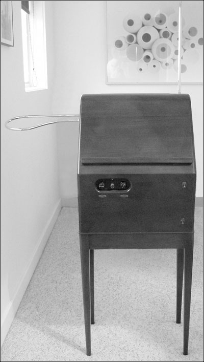
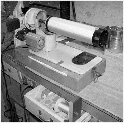
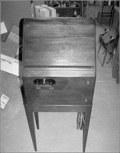
Figure 1. Mark McKeown's restored RCA Theremin. The pitch antenna is on the top and the volume antenna is on the side.I have always wanted an original RCA Theremin, and knowing that I would never own one, last year I built a replica using mostly vintage parts and the original physical layout. Building my second Theremin resulted in a thorough knowledge of how it was constructed and how it worked electronically.
I also have been restoring antique radios for the past ten years. This background combined with a fanatical desire for authentic restoration set the stage for the RCA Theremin restoration project reported here. The result is my third Theremin, completely restored and shown in Figure 1 above right.
Disassembly
All the following photos assume one is facing the back of the Theremin. Photographs of everything before disassembly are extremely useful during the restoration and reassembly process. If in doubt, draw a sketch. Not only will you have a record but you will better understand what has been done. It is a lot easier to draw a sketch now than try to figure it out later. Wire color coding in this set was the same as in the RCA manual, although some fading of the power supply cable wires had occurred.
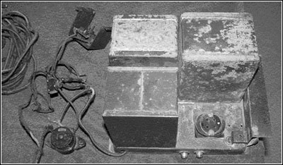
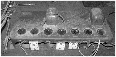
Figure 3. The power supply in rather poor cosmetic condition. Inside the metal cans are the transformer, choke and filter capacitors. The tube socket is on the lower right.I carefully removed all the tubes, keeping in mind that the sockets were delicate. The nuts on the front panel switches were hard to loosen. I used a pair of pliers with duct tape on the jaws to keep from scratching the bezels and cabinet. Not doing damage now means less to repair later. I noted that the lower on/off switch bezel reads up side down; it came that way.
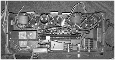
Figure 5. The underside of the main chassis.I then removed the pitch and volume coils from the chassis shelf. I used small wrenches or nut drivers to loosen the nuts on the wire terminals. Pliers chew up whatever they touch. The terminals were spade lugs, except for the antenna wire lugs. These were inconveniently of the ring type, so the nuts had to be removed, dropped and found. Each coil is fastened to the chassis shelf with bolts. The bolts on the chassis side have to be very carefully removed to keep from damaging the coils.
The Theremin was then placed next to a table on the left side of the cabinet. The chassis/shelf was then removed from the case, rotated around and set on the table while the cable to the power supply was disconnected. The chassis shelf is fastened into the cabinet by a screw on each end.
As Figure 2 shows (see print version), the power supply cable does not use all the power supply terminals (discussed below). The cable is formed so that each wire almost automatically wants to go on the right terminal. The correct layout is in the RCA manual if needed, although a sketch and photograph of the hookup is a good idea before removing the wires.
After sliding out the chassis/shelf, I set the unit on a small box so that the unit was not resting on the power supply cable. The cable goes through a hole in the shelf and can easily be bent or damaged. The old cloth-covered wire insulation is very delicate.
I then unfastened the accessory socket, switches from the cabinet front, and the safety interlock switch bracket. The AC power cord was then pulled through the hole in the cabinet bottom. After removing the four screws that held the power supply to the cabinet bottom, I removed the power supply.
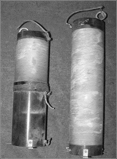
Figure 9. The damaged volume, left, and pitch coils.Power Supply Chassis
The power supply, shown in Figure 3, is typical of the time (1928), utilizing three chokes to do much of the filtering because high value capacitors were very large. I cleaned the underside of the power supply, shown in Figure 4 (see print version), using lots of Q-Tips, 409 or paint thinner, or both, depending on what worked best. I applied power to the supply without a rectifier tube with a Variac, slowly increasing the voltage. The transformer voltages were within specifications so I installed a Type 80 rectifier, the modern equivalent to the Type UX-280. Why risk a vintage tube?
Again using the Variac, I increased the line voltage output. Voltages were still within specifications, so I let the power supply cook for a few hours. The filter capacitors are typically bad in these old power supplies, but these appeared to be good. I then used the power supply to power the replica RCA Theremin I had constructed, and everything worked fine.
The power supply used by RCA in the Theremin is identical to the supply used in the RCA Radiola 60 radio that was produced at the same time. The only difference is that terminals 3 and 4 and terminals 6 and 7 are shorted together, removing one output voltage and grounding another terminal. Because these power supplies are available, I was not too worried about the capacitors.
Main Chassis
The underside of the main chassis, shown in Figure 5, was in good condition with all components in relatively good physical condition. Again, I cleaned the underside of the power supply using lots of Q-tips, 409 and paint thinner. All nuts and bolts were checked for tightness. Metal can corrode, and anything not made of metal can shrink in 77 years, so these were carefully checked. The variable capacitor frames were fiber board, and the through bolts were loose. All resistances were checked and were close to nominal. The values of carbon composition resistors are often not close to the original values because carbon resistors can change radically with age. In this case, the resistors were all within a few percent. For some reason the resistors were not color coded.
The power cable was constructed of cloth-covered wire that was laced together. The insulation was very fragile so I wrapped the cable with roll bandage to protect it. This protective covering is shown on the left side of Figure 6 (see print version). Typically a chassis gets flipped over numerous times during repair and restoration so extra care was necessary to protect the cable.
All the bypass capacitors were in large cans. The capacitors were bad so these I rebuilt. Each can was disassembled, a spacer block was made and a much smaller modern replacement was installed in the cans. A typical rebuilt capacitor is shown in Figure 7 (see print version). The cans were then sealed, painted and new labels made. A scanner and color printer are invaluable for doing this work. The damaged labels were scanned, repaired bit-by-bit, and then printed. Figure 8 (see print version) shows the restored capacitors.
Figure 10. The "Singer" coil-winding lathe. In the lower center of the photograph, note the spool of wire which is being wound onto the right end of the pitch coil on the lathe.The three oscillator coils, fortunately mostly protected by the chassis, were in good shape. The double cotton-covered wire looked intact. The chassis was too shallow for the coils probably because it was the same as used for one of RCA's radio models. The chassis was mounted on strips of wood to get the necessary clearance beneath the chassis for the coils. The parallel capacitors used in the oscillators were mica and were in excellent shape. If you looked close, the capacitance of each capacitor could be seen hand-written on the outside.
The audio transformers checked OK and had appropriate DC resistances. This was fortunate since rewinding audio transformers is a tedious process. The transformers had part numbers on the can, and these turned out to be the same audio transformers used in Radiola 60 radios.
Pitch and Volume Coils
Unfortunately, someone had removed and lost the two back cabinet doors exposing the large pitch and volume coils to damage. These coils, shown in Figure 9, were wound with double cotton-covered wire and had been scraped. The wires were broken and the insulation rotted. Fortunately, the forms were undamaged.
Because these coils are the heart of the instrument electronically and help give the instrument a vintage look, using the appropriate wire was very important. Getting the wire made in the small quantity needed was not practical, so I checked with some antique radio forums on the internet. I was fortunate to find Alan Douglas (author of numerous antique radio publications) who donated the vintage #38 wire needed for the restoration.
Winding coils this size with #38 wire by hand is difficult. I decided to build a coil winding lathe out of a sewing machine. I purchased a nice Singer sewing machine for $2 at a rummage sale. I disassembled the unit as much as possible and then cut the main frame of the machine off with a cutoff wheel in a body grinder -- brutal but effective. The foot control was very useful but the speed was too fast so I used a gear reduction from a World War II radio control head to reduce the speed.
Figure 15. The main chassis before refinishing.The machine had to be turned around and used from the back side to get the rotation in the right direction for coil winding. I made two hubs to hold the coil form on the sewing machine main shaft. The "Singer" coil winding lathe made winding the coils much easier. The coil-winding setup is shown in Figure 10.
Cotton-covered wire is very sensitive to kinking which damages the insulation, so the coil lathe was well worth the effort. Before winding the coils, I sprayed the form with satin Rustoleum enamel which dries very slowly. When the paint became tacky, I wound the coils, taking advantage of the tacky paint to help hold the windings in place. The resultant coils are identical to the original and are shown in Figures 11 and 12 (see print version). The pitch coil has a "concentrating" coil located inside at the base which was in good condition. Figure 13 (see print version) provides end views of the coils.
Theory of operation of coils
Volume Control.
The RCA Theremin uses the Type 120 tube to vary the audio gain by varying the tube filament voltage (i.e. filament temperature) and therefore the amount of current flowing through the tube. Many early 1920s radios used a rheostat to control the filament voltage and basically the same method to control the volume.
Figure 18. The restored main chassis (left) and the power supply chassis.Hand capacitance applied to the antenna on the side of the Theremin is used to vary the oscillation frequency of the volume variable oscillator. The output of the volume variable oscillator is mixed (heterodyned) with the output of a fixed oscillator. As the resonant frequency of the volume variable oscillator, which is varied by hand capacitance, approaches the resonant frequency of the volume fixed oscillator, more current flows in the large coil and therefore in the secondary of the large coil which powers the 120 filaments.
Pitch Control. The pitch control coil likewise uses hand capacitance to vary the oscillation frequency of the variable oscillator. The output of the variable oscillator is mixed (heterodyned) with the output of the fixed oscillator. The result is the audio frequency we hear.
Front Panel
The chassis had a black Bakelite panel mounted on the front that is visible through the hole in the cabinet that exposes the tuning capacitors and pilot light. I painted the panel satin black and fitted a replacement jewel for the light to the original jewel holder.
Antennae
The previous owner of the instrument had replacement antennae made. These were made of 7/16" in diameter brass tubing. The antennae are plugged into sockets on the case. The replacements were exact duplicates of the original (there was a damaged pitch antenna for comparison). All I had to do was get them and the original sockets nickel plated to match the original and look new. Figure 14 (see print version) shows the replated pieces.
Initial Operation
In order to test the pitch and volume sections separately -- not expecting either section to work -- I put three volts on the Type 120-tube so that the volume part of the circuit would have the volume all the way up. Amazingly enough, after the smoke test was successful (no smoke), the pitch circuitry worked fine from the start, and I had only to tune the unit as described in the RCA Service Notes.
I then removed the three volts from the 120 tube and had no sound. I checked to see if the oscillator was working, and it was, but not near resonance with the large coil. I then removed the capacitance that was in parallel with the oscillator coil and installed a mica compression trimmer so I could "tune" the circuit. I tuned the circuit to proper resonance and then measured the capacitance needed. The needed capacitance was less than the original fixed mica capacitor, but I was able to disconnect one of the plates between the mica leaves and then add a small mica capacitor to get the correct parallel capacitance. The small mica capacitor is hidden underneath the original capacitor. I could have added or removed turns from the large coil but chose to change the capacitance because this seemed less drastic.
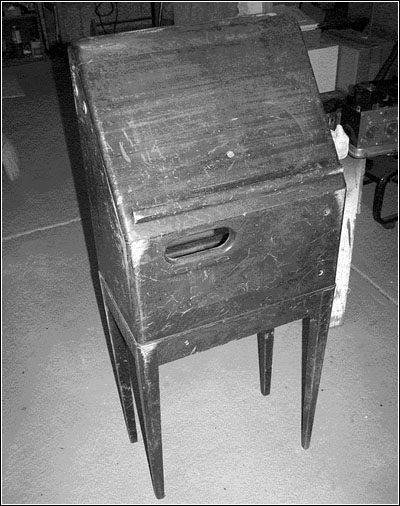
Figure 19. The cabinet before restoration.Refinishing the Power Supply and Chassis
The power supply chassis and the main chassis had originally been painted brown. The transformers and potted chokes and capacitors were in large rectangular cans or small cans that were also painted brown. Figure 15 shows the main chassis in its original state. Everything was rusted and pitted, so I removed as many screws (sometimes sequentially) as possible and sanded the chassis to remove loose paint and rust. Every screw, bolt and nut that was removable was taken off and cleaned with a small wire brush. I made cardboard discs to mask the tube sockets, as shown in Figure 16 (see print version).
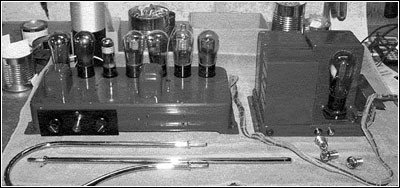
I then sprayed the power supply and chassis with red primer. The primed chassis is shown in Figure 17 (see print version). After sanding the primed power supply and chassis, I painted both with leather brown Rustoleum gloss enamel. This color closely matched the original brown paint. The restored main chassis and power supply chassis are shown in Figure 18.
Figure 20. Patches of wet paper towel secured with mylar tape help dent removal.The bracket that holds the ceramic trimmer capacitors on the back of the chassis had to be removed and refinished because it was rusty. Black satin enamel was used for this part of the project.
Refinishing the Cabinet
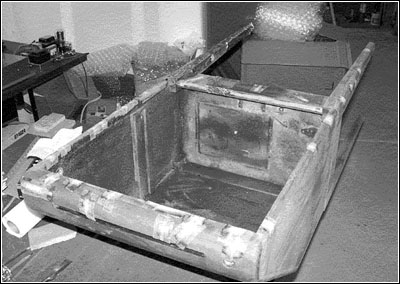
The cabinet was covered with numerous scrapes, gouges and dents, as Figure 19 shows. Apparently not everyone cherished the instrument as we would now. I took small wetted bits of paper towel and used mylar tape to hold them over the dents for a day to let the wood swell and fill the holes. The patches are shown in Figure 20. I filled what remained with plastic wood as necessary until the cabinet was repaired and ready for refinishing.
The cabinet apparently spent part of its life in a humid climate because almost every glued joint was loose. I carefully aligned, glued and clamped joints, and added screws if they could be concealed, until the cabinet was again tight. The gluing and clamping operation is shown in Figure 21 (see print version). I then stripped off the old finish.
The beading between the cabinet base and top was either missing or torn up so I constructed new out of mahogany. The two doors on the back of the cabinet had been removed so I had to construct new ones. The original instrument was made of solid mahogany with the base and back doors made of mahogany-veneered wood. I had to find two flat pieces of wood, use a planer to reduce the thickness by two layers of veneer, and then glue the veneer to the wood to get the right material in kind and thickness to replace the doors. I also had to make the safety interlock brackets that fasten to the door. These close the interlock switches when the doors are closed allowing the mains power to be turned on with the front panel switch.
RCA apparently did not do anything beyond what was normally done for finishes on their production radios. The cabinet was made by the Jamestown Mantel Company, manufacturers also of Radiola 60 radio cabinets. I refinished the cabinet by staining the unit with walnut to match the original finish, applying a coat of lacquer sanding sealer, and a coat of satin clear lacquer. The satin finish is closer to a vintage finish than a shiny new gloss lacquer produces. See Figures 22 (se print version), 23, and 24.
Figure 23. A front view of the restored Theremin.Miscellaneous
During construction of the replica RCA Theremin I discovered that there were many electronic part values and mechanical and physical dimensions of the instrument that were unknown. As part of the restoration project, I measured all the electronic part values and coil dimensions. This was to check the information I was able to find and had developed for my earlier replica construction so that the instruments could be more easily and correctly duplicated. I also made dimensioned drawings of the cabinet so the cabinets could also be duplicated, although the dimensions could be obtained from other Theremins in collections.
A Type 31 tube can be substituted for the Type 120 tube but the response time is a little slower. I made a socket adapter and used a Type 3Q4 miniature tube, and it works about as well as the 120 and is easy and cheap to obtain. A Type 01-A tube can be substituted for the Type 171A audio amplifier and actually works better. A 171A is necessary in the volume oscillator because the 01-A will not oscillate.
Figure 24. A rear view of the restored Theremin.This instrument is like radios of the time, requiring a high impedance speaker. Modern speakers have impedances between 4 and 16 ohms and a high impedance speaker is around 2000 ohms. A modern speaker can be used, but an impedance matching transformer is appropriate between the instrument and the speaker.
The serial number of the instrument is stamped on the top of the main chassis. The serial number of this instrument is 100247 which correlates with other reported numbers. I don't know what the number on the doors means.
Conclusions
This project was a challenge from start to finish. Perseverance in finding obsolete parts and materials and a strict adherence to the original construction resulted in a restoration that would be difficult to detect. The measurement of values and dimensions during the restoration made available critical information that allows duplication and repair of the original instrument electronically as well as physically.
Remember that this instrument uses lethal voltages with which many transistor era constructors are not familiar.
Reference:
RCA Victor Service Notes. Camden, N.J.: RCA Manufacturing Co., Inc., 1929-1930.
Thanks to David Kean and the Audities Foundation in Calgary, Canada, for providing me the opportunity to restore an original RCA AR-1264 Theremin, an opportunity of a lifetime. (Mark McKeown)
Thanks also to Alan Douglas for supplying the much needed wire.
The information in this article first appeared on the Theremin World Website at www.thereminworld.com.
Copyright © by Mark McKeown, 2006
(Mark McKeown, 14707 Mouse Ear Ln., Golden, CO 80403)
Mark McKeown has collected and restored antique radios and communication gear for about ten years. Having built his first Theremin in the 1970s, he also restores other vintage electronic musical instruments. An Amateur radio operator since the age of 14, he has held an Extra Class Amateur Radio license for 51 years.
| [Free Sample] [Books, etc., For Sale] [Subscribe to A.R.C./Renew] [Classified Ads] [Auction Prices] [Event Calendar] [Links] [Home] [Issue Archives] [Book Reviews] [Subscription Information] [A.R.C. FAQ] URL = http://www.antiqueradio.com/Aug06_McKeown_Theremin.html Copyright © 1996-2006 by John V. Terrey - For personal use only. Last revised: July 27, 2006. For Customer Assistance please contact ARC@antiqueradio.com or call (866) 371-0512 toll free Pages designed/maintained by Wayward Fluffy Publications
Antique Radio Classified |