Of Old Radios And Related Items--Published Monthly
A Kroehler with a Twist
By Jerome Wieland
WEB EDITION
Every collector knows the joy of a flea market where the unexpected turns up. Then, of course, comes the challenge of finding out more about the mystery set you can't resist buying and restoring it. Jerry Weiland takes us through the familiar process. (Editor)
My favorite radio hunting location these days is the flea market at the county fair grounds. Every month, including winter, vendors display all sorts of interesting stuff, including the occasional radio. This July, as I rounded a corner, I spotted a wide, rounded tombstone on a table. Even at a distance, it looked old and interesting. The metal escutcheon bore the name "Kroehler." The vendor said Kroehler was a furniture manufacturer. The cabinet was in decent condition and all the tubes were there. The price was high at $90, and he wasn't in the mood to deal, but I couldn't leave without it. The radio is shown in Figure 1.
At home, a check of the Internet revealed very little information about Kroehler. I did find a furniture company in Wisconsin, but no reference to radios. A check of sites with photos uncovered one Kroehler tombstone but not mine. The free schematic sites had no Kroehler reference.
Internal Investigation
I removed the chassis from the cabinet and examined the cabinet closely for further clues. There was nothing to be found. The chassis nameplate contains a serial number and the Kroehler Manufacturing Corporation name. The chassis contains six tubes and is a TRF design. The tubes types are three 24s as RF amps, a 27 detector, a 45 audio amp, and an 80 rectifier. The speaker is an 8-inch Rola electrodynamic with a chassis plug, which I appreciate since it makes chassis removal much less complicated.
Once the chassis was removed and vacuumed, it could be closely inspected. The 3-gang tuning capacitor was in good condition, but oddly had the remains of wires on each stator terminal at the top of the assembly. The two electrolytic filter capacitors in the power supply are housed in copper cans that screw into copper holders attached to the chassis. This is rather unusual. The hot lead exits the top of each capacitor. Interstage RF coupling coils are housed in shield cans as are the three RF amplifier tubes. A large power transformer and a power supply choke are also mounted on top of the chassis. An audio coupling transformer is also shielded.
Turning the chassis over revealed some problems. Two multicapacitor cans were riveted to the chassis and were leaking wax. No value markings could be found on the cans. The audio coupling transformer was potted in black tar and had been overheated causing black slime to flow over the wires and components in the area.
Repair Procedures
Before committing to any repairs, I like to assure myself that the power transformer is alive. I do this with all the tubes removed and a 120v light bulb connected in series with the primary. I slowly apply power to the primary through a variac increasing the voltage slowing while watching the bulb and monitoring the high voltage transformer output with an AC voltmeter. Ideally, there should be no smoke, flames, or noise. The output voltage should be between 300 to 700 volts, and the bulb should not light or at most glow very dimly. Significant glowing indicates leakage or a short. Mine passed the test.
With this many obvious problems, there were probably other less obvious issues to be found. A schematic is very helpful when you need to determine what function various components are performing. I had some unidentified parts that would need to be replaced, and I did not know the original values. Since I could not readily find a schematic on the Internet, I decided to draw my own.
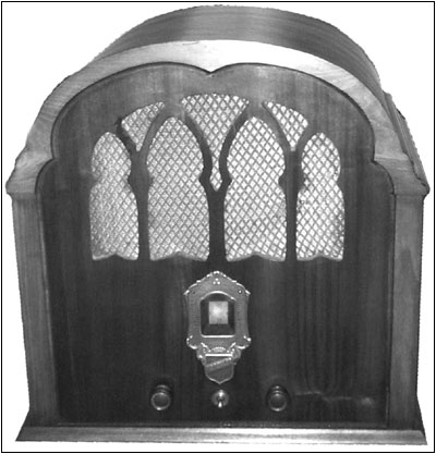
Figure 1. This screen-grid is labeled with the name "Kroehler."
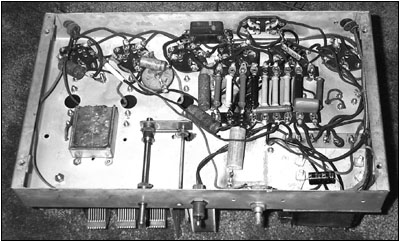
Figure 2. An underside view of the chassis shows the component layout, including the replacement filter capacitor.
Single-band receivers are not very complicated, and TRF designs are even less complicated compared to superheterodyne types. An hour of tracing wires resulted in a decent schematic. Most of the leaking multistage caps were RF bypasses in cathode circuits. A 0.1uF value is typical for this function. One was the detector cathode bypass which I chose to replace with an 0.1uF since audio may be present.
Next I checked the continuity of the RF coupling coils and the audio transformer. I was pleasantly surprised to find all were OK. I also noticed supply chokes were used in each RF amplifier plate circuit. One of the three was open. I replaced it with a modern choke from my spare parts supply. Value is not critical in this application.
A check of the two power supply filter capacitors showed one to be completely open, but the other still seemed functional. Since they were single-stage 8uF/450v types, I decided to replace both. I left each original filter capacitor screwed in the chassis for appearance, disconnected the hot lead under the chassis, and then wired a new cap out of sight. In my more ambitious (younger) days I would have gutted the old cap cans and mounted a new cap inside. This now seems like too much work for something practically no one will ever notice. An under-the chassis view of the radio is shown in Figure 2.
All told, I replaced nine parts before considering a full functional test. All tubes checked OK and were inserted into their respective sockets. All sockets had the tube number marked on them making it easy to get them in the correct locations. I connected an antenna wire and slowly increased the line voltage with my Variac. The radio came to life with a satisfying sound of a weak station. Tuning around revealed more stations. Tweaking the trimmers on the 3-gang tuning capacitor peaked the stages and resulted in very good reception for this type of design.
I was very pleased with myself until I noticed that the stations were not tracking correctly on the dial. The dial was calibrated in large 0 to 100 numerals with smaller 575 to 1500 kHz marking in between. The low frequency stations were on the high end of the dial and visa versa. The drum dial has a semicircular plastic strip which appears in the small dial window of the escutcheon. Two dial cords are used to pull the wheel in either direction.
No amount of repositioning or restringing would make the dial track correctly. I began to wonder about the 3-gang tuning capacitor. Those cut wires on the top might be a clue as to what caused the tracking problem. Examining the connections to the gangs revealed that the three wires to the TRF stages were not soldered, but wrapped around screws. This did not appear to be the original connection method. It was more likely that they were soldered to the lugs at the top of the assembly. It appeared that if I turned the whole tuning capacitor assembly 180 degrees the dial would track correctly.
One slight issue still remained however. The tuning capacitor shaft was now too short to mount the drum dial on. In fact, the shaft on this side was flush with the capacitor housing and it needed to be about two inches long. Since I had gone this far, I was determined to make it work. To extend the shaft, I would need to graft an extension to the stub. To do this, I found a metal pin of the same diameter and cut it to length. I drilled pilot holes in the pin and capacitor shaft suitable for tapping 4/40 threads.
After tapping, I cut the head off a 4/40 screw and threaded it into the cap shaft after coating the threads with super glue. I then threaded the shaft extension onto the protruding screw also coated with super glue. When tightened, the extension exhibited minimum wobble since I took care to drill the holes as close to dead center of the shafts as possible. After drilling a few mounting holes, remounting the tuning assembly, and restringing the dial cords, the dial tracked properly. I connected the TRF leads to their proper locations at the top of the gangs.
Apparently, the tuning capacitor assembly was not original. During disassembly, I noticed that additional mounting holes had been drilled in the frame. Some of the mounting brackets appeared to be handmade also. However, the assembly fit well and worked electrically. Someone took great pains to replace this assembly and did a rather nice job except for the tracking problem.
I refinished the cabinet keeping the original grille cloth. The photos show the final product. I would appreciate some information on the Kroehler Company and their radios, particularly this model.
(Jerry Wieland, 780 Charleston Ln. Hoffman Estates, IL 60195)
Jerry Wieland is an electrical engineer working in cellular phone development at Motorola. His interest in old radios began at age 12 when he started listening to shortwave broadcasts on a 1930s Silvertone console.
�
| [Free Sample] [Books, etc., For Sale] [Subscribe to A.R.C./Renew] [Classified Ads] [Auction Prices] [Event Calendar] [Links] [Home] [Issue Archives] [Book Reviews] [Subscription Information] [A.R.C. FAQ] URL = http://www.antiqueradio.com/Dec03_Wieland_Kroehler.html Copyright © 1996-2003 by John V. Terrey - For personal use only. Last revised: November 28, 2003. For Customer Assistance please contact ARC@antiqueradio.com or call (866) 371-0512 Pages designed/maintained by Wayward Fluffy Publications
Antique Radio Classified |