
Of Old Radios And Related Items--Published Monthly
Capacitor Tips for the Beginner
BY DAVE CANTELON
Web Edition
Capacitors can be puzzling to someone new to radio repair. When you're in the midst of a repair job, Dave Cantelon's simplified capacitor tips should be helpful. (Editor)
If you are new to restoring antique tube radios, here are some useful capacitor tips. How to choose capacitors and install them in tube radios is explained in nontechnical language. Have fun and good luck with your vintage radio restorations.
Tube Radio Capacitors -- The Basics
· Your vintage tube radio needs both direct current (DC) and alternating currents (AC) to operate. Capacitors act to pass AC while blocking DC. Capacitors are used to block, pass, filter and tune the various voltages and signals in your radio.
· Don't let terminology confuse you. A "condenser" is just an old-fashioned name for "capacitor."
· Capacitors have a capacitance value and a voltage rating. The capacitance value is a measure of how much electric charge a capacitor can store. The voltage rating is the maximum voltage the capacitor can handle without breaking down.
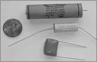
Figure 1. A typical old paper-dielectric capacitor, top, can be replaced with either an axial-lead capacitor, center, or a radial-lead, plastic film capacitor, bottom. The penny at left shows the comparative size of the capacitors.· Your old tube radio uses four types of capacitors: variable (tuning) capacitors, mica capacitors, paper capacitors and electrolytic (filter) capacitors. When you restore an antique radio you will replace the paper and electrolytic capacitors, but not the variable capacitors. Mica capacitors seldom need replacement.
· In radio service literature, such as Sams Photofacts, paper and electrolytic capacitors are usually expressed in terms of "microfarads." Short forms for microfarad include mfd, MFD, MF, and uF. The mica capacitors in your tube radio will have lower capacitance values than the paper and electrolytic capacitors. Micas are expressed in terms of micromicrofarads or picofarads. Short forms for micromicrofarads include mmfd, MMFD, MMF, PF and pF. A pF is one-thousandth of a uF. For example, a mica capacitor valued at 500 mmfd (pF) would be 0.0005 mfd (uF).
· As a general rule, if a capacitor in your vintage tube radio is less than 0.001 uF, it is probably a mica capacitor. If it is between 0.001 uF and 1.0 uF, it is likely a paper capacitor, and if it's more than 1 uF, it's probably an electrolytic capacitor.
· Sizewise, the electrolytics are the largest capacitors, and most tube radios use two or three of them. The original electrolytic capacitors are typically the size of a roll of quarters or larger. On the old AC sets, they are usually encased in aluminum and mounted on top of the chassis. With the lightweight AC/DC sets of the 1950s, they are quite often under the chassis and may have a cardboard case.
· The original paper capacitors in your radio will likely be in a paper tubular case sometimes coated with wax. They are usually 1 to 11/2 inches long and 1/4 to 1/2 inches in diameter.
· Mica capacitors come in different sizes and shapes, but the most common shape is square or rectangular. Often, they are brown in color with colored dots, looking a bit like dominos.
· Capacitors have either radial leads or axial leads. With the radial type, both leads exit from the same end of the capacitor. With the axial type, there is a lead at each end of the capacitors. Both types are equally good. Just be sure the capacitors you use have long leads.
· On schematic diagrams, a fixed capacitor can be represented in two ways:
Modern film capacitors are nonpolar, like the symbol on the left, so you don't have to worry about polarity when replacing old paper caps with new film capacitors. If there is a curved side, as on the right, the flat side of the capacitor symbol is the positive (+) side and the curved side is the negative (-) side. The positive end must be kept at the higher electrical potential (more positive voltage).
· How about using New Old Stock (N.O.S.) capacitors? These are not recommended -- use at your own risk! As paper and electrolytic capacitors age, their capacitance values drift, and they dry out or become leaky. Would you drive a 1930s automobile with N.O.S. 70-year-old tires?
· Don't waste your money on audiophile, computer grade or tantalum capacitors. Sure they are good capacitors, but your old tube radio does not have the electronic circuitry to take advantage of those expensive capacitors. The only difference you will notice is a lighter wallet.
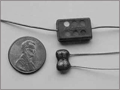
Figure 2. New mica capacitors are also smaller than older micas.· Plastic/polyester film capacitors are now used in place of paper capacitors due to their smaller size, lower cost and superior performance. There are many variations of plastic/polyester capacitors. Good types of film capacitors for tube radio restorations include metalized polyester, metalized polypropylene, metal-foil polypropylene and Mylar. What is Mylar? Mylar is simply the trade name of the synthetic film registered by du Pont. Figure 1 shows an old paper capacitor, top, and two present day film replacements -- an axial lead, center, and a radial lead at the bottom.
· At higher frequencies, polypropylene is more stable than polyester, so for film capacitors under 0.01 mfd, you may want to use polypropylene capacitors rather than polyester capacitors.
· What should it cost you to replace the capacitors in your radio? To "recap" a typical 5-tube radio you will need a couple of electrolytic capacitors and about a dozen film capacitors. Total cost for these parts should be $10 or less.
Nonelectrolytic Capacitor Tips
· When replacing old paper/wax capacitors, you can't go wrong using film capacitors that have a higher voltage rating than the paper ones you are replacing. For example, if you are replacing a paper capacitor rated at 400 volts, you can use a 630-volt film capacitor (but not a 200-volt capacitor).
· Why were tube radios manufactured with 200-, 400-, 600-volt paper capacitors if 600-volt could have been used for all the capacitors? Two reasons -- cost and size. Capacitors used to be expensive, so if a manufacturer could use lower voltage capacitors in a circuit, it could cut production costs. Also, the higher the voltage the larger the paper capacitor, so it was easier to install lower voltage paper capacitors. Nowadays, film capacitors are inexpensive and compact, so use 630-volt film capacitors and you can't go wrong.
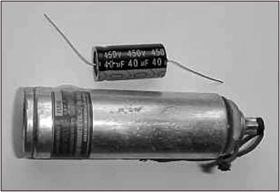
Figure 3. Improved manufacturing technology has reduced the size of electrolytic capacitors. Compare the size of an old capacitor, bottom, with a new equivalent, top.· Radio schematics and/or parts lists sometimes do not specify the working voltages of nonelectrolytic capacitors. To be safe use a film capacitor rated at 630 volts.
· Old paper/wax capacitors are one of the most unreliable parts in an old radio. Don't let "molded" paper capacitors fool you. They are just paper capacitors in plastic cases and are just as unreliable as the ones coated in wax.
· Modern nonelectrolytic capacitors -- i.e. mica capacitors, film capacitors, ceramic capacitors, etc. -- are nonpolar. This means you don't have to worry about which end to connect when replacing old paper capacitors with new film capacitors. As Figure 2 shows, new mica capacitors are also smaller than their old counterparts.
· Although nonpolar, old paper capacitors had black bands at one end to indicate which wire lead was connected to the outside foil. The end with the outside foil was connected to the ground or lowest voltage.
· When replacing paper capacitors with film capacitors keep in mind that capacitance values are "easy to please." The uF value does not need to be exactly the same. For example; if replacing a 0.05 uF capacitor, you can use a 0.047 uF; if replacing a 0.002 uF, you can use 0.0022 uF. These replacements are virtually identical. If you are plus or minus 10 percent, you will usually be well within your radio's factory specifications. (Just be sure your replacement capacitor has a working voltage equal or greater than the original paper capacitor)
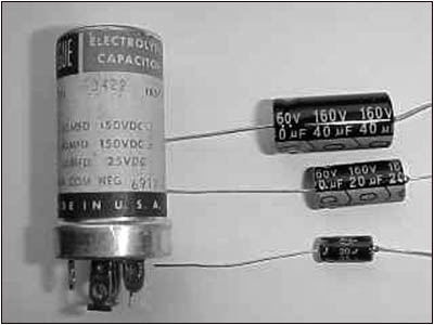
Figure 4. Because of their small size, the three electrolytic capacitors are easily installed under the chassis as replacements for the 3-section electrolytic shown at the left.Electrolytic Capacitor Tips
· Electrolytic capacitors are often referred to as "filter capacitors." Electrolytic capacitors help to filter AC (alternating current) power from the DC (direct current) voltage that your radio tubes need to operate.
· Sizewise, the electrolytics are the largest capacitors. With older sets they are usually encased in aluminum (can type) and mounted on top of the chassis. If they are not on top of the chassis you will find them under the chassis.
· Capacitors used to be much larger and much more expensive than they are today. Figure 3 shows an older can-type electrolytic capacitor and a currently available replacement. An old multisection electrolytic and its replacements are shown in Figure 4.
To save on space and cost "multiple section" electrolytics were used. These are simply two, three or four capacitors in the same case. You will notice just one ground connection (black wire) as all the caps usually share that ground. For the can-type capacitors that sit on top of the chassis, the metal can itself is very often the ground. These "multisection" caps can be replaced with several single electrolytics. Modern electrolytics are compact and will easily fit under the chassis. You should leave the old can capacitor on the chassis for original appearance. Just be sure to disconnect it.
· Electrolytic capacitors work hard and are probably the most unreliable part of an antique radio. As they wear out, you get that famous "tube radio hum." Yes, in most cases it is bad filter capacitors that are the cause of that hum. Warning! If your tube radio hums, turn it off and don't use it. Bad electrolytics are not only hard on your ears, but also hard on the tubes, transformers and other parts in your radio. Capacitors are cheap, but tubes and other parts can be expensive and hard to find.
· Electrolytic capacitors have a rated "working voltage" (WV) which is the voltage they can handle. Ideally, an electrolytic capacitor should be operated at a voltage no greater than 3/4 of its maximum working voltage. Never replace an electrolytic with one that has a lower voltage rating.
· As with paper capacitors, the capacitance value of an electrolytic capacitor is "easy to please," and an exact uF replacement is not necessary. For example, you can replace a 30 uF with a 33 uF or replace a 20 uF with a 22 uF. If you can't find a close replacement , it is better to go with a higher uF value than a lower.
· If you replace an electrolytic capacitor with one that has too low an MFD, your radio will hum.
· On the other hand, if you replace an electrolytic capacitor with one that is too high in value, voltages may be higher than called for.
· Warning! Electrolytics have a negative end and a positive end. If you install an electrolytic with the polarity reversed, not only will your radio not work, but the electrolytic capacitor could explode.
· As a general rule, AC (tube radios with power transformers) can use 450-volt electrolytics while lightweight AC/DC tube radios can use 160-volt filter capacitors. However, there are exceptions, so it's always best to refer to a schematic.
· Electrolytic capacitors have a shelf life of a couple of years, after which they may need to be reformed. So, make sure you buy "fresh" stock electrolytics (not new old stock). Would you buy a stale loaf of bread if a fresh one were available?
· Electrolytic capacitors should be stored at temperatures of 5 to 35 degrees C (40 to 95 degrees F) and in nonhumid conditions (less than 75 degrees relative humidity) to maximize shelf-life.
· Don't put your tube radio into storage after you have restored the electrics. Once a month, let the radio sing for a half hour or so. This will reform the electrolytic capacitors.
Capacitor Installation Tips
· When restoring an antique radio, it is standard practice to replace certain of the radio's capacitors. This is known as "recapping" a radio. An old radio may work with its original caps, but for how long? And how safely? If the radio is going to be sold with a guarantee or is being given to someone as a gift, you should "recap" the radio.
· You will want to replace all the paper and electrolytic capacitors. However, do not replace the mica capacitors. Mica capacitors very rarely go bad, and if you replace them, it will throw off the radio's tuning. Replacing the mica capacitors will do more harm than good. Replace a mica only if you are sure it is bad.
· Like mica capacitors, ceramic capacitors also very rarely go bad. Do not replace ceramic disc capacitors unless you are sure one has gone bad.
· Get a schematic and parts list before you start your recap job. It is often impossible to read the values that are on the original capacitors. Also, if the radio was repaired at some time in the past, there is a good chance someone threw in the wrong size capacitors, just to get the radio working. Without a schematic, you'll be guessing.
· While replacing the capacitors, check the radio's resistors. Since you will be replacing the capacitors, you should snip one lead of each paper and electrolytic capacitor. This will help prevent false resistance readings.
· Put insulated tubing spaghetti on the leads of the capacitors and resistors before you solder them into the circuit. This will help prevent dangerous shorts.
· Always check a capacitor before installing it. Although it is very rare, every once in a blue moon, a new capacitor will be defective or off spec. Taking ten seconds to check a capacitor can save you hours of troubleshooting, only to find out you accidentally installed a brand new "bad" capacitor.
· If you need a higher uF than is available from your retailer, you can connect a couple of capacitors in parallel (side-by-side). For example, if you need 200 uF at 450 volts, you could connect two 100 uF 450-volt capacitors in parallel, and you would end up with 200 uF at 450 volts. You have kept the voltage the same while doubling the uF.
· If you need a higher working voltage, you can connect a couple of capacitors in series (end-to-end). For example two 100 uF at 450 volts in series would give you 50 uF at 900 volts. You have doubled the voltage and halved the uF.
· Last but not least, remember to work safely. The high voltages stored in large capacitors can kill! Before you work with these capacitors, they should be completely discharged. This can be achieved by connecting (bridging) the two ends of the capacitor in question with a high wattage 1,000-ohm resistor, using insulated clips and leads.
I hope you found the above information helpful. If you have any capacitor questions, feel free to contact me.
(Dave Cantelon, Just Radios, 42 Clematis Road, North York, Ontario, Canada, M2J 4X2. Phone: 416-502-9128 Email: justradios@yahoo.com Website: www.justradios.com.)
Dave Cantelon is an admitted antique radio addict who loves nothing more than bringing back to life an old tube radio, especially pre-World War II AC sets. Dave is active in a number of Antique Radio Clubs in Canada and the USA and is currently treasurer and membership chair of the London Vintage Radio Club (LVRC). Dave and his better half Babylyn run the website www.justradios.com, which specializes in capacitors and schematics for vintage tube radios.
| [Free Sample] [Books, etc., For Sale] [Subscribe to A.R.C./Renew] [Classified Ads] [Auction Prices] [Event Calendar] [Links] [Home] [Issue Archives] [Book Reviews] [Subscription Information] [A.R.C. FAQ] URL = http://www.antiqueradio.com/Dec04_Cantelon_capacitor.html Copyright © 1996-2004 by John V. Terrey - For personal use only. Last revised: November 27, 2004. For Customer Assistance please contact ARC@antiqueradio.com or call (866) 371-0512 Pages designed/maintained by Wayward Fluffy Publications
Antique Radio Classified |