Of Old Radios And Related Items--Published Monthly
Templetone Model BP2-A5 "Morale Radio"
A Restoration
BY DANIEL SCHOO
Web Edition
This is Daniel Schoo's third article based on his work restoring the Templeton set. The first dealt with paper capacitor rebuilding (A.R.C., October '09); the second with dial cover making (A.R.C. December '10). Now Dan gives us the full story of this restoration. (Editor)
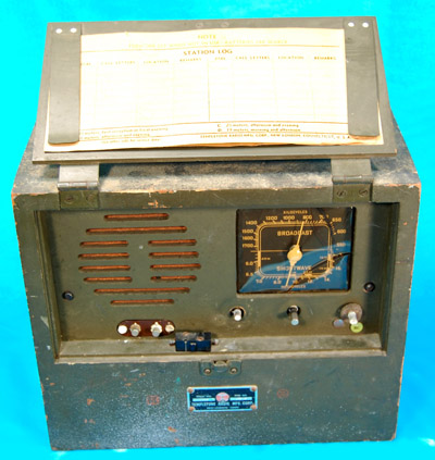
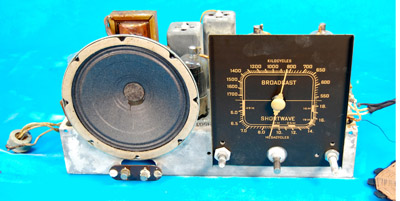
One day my wife Donna came home to find another orphan left on the doorstep. She e-mailed me at work and told me that there was an "old junk radio" in the driveway. When I got home I found a cute little military radio in fairly good condition considering its past. The set as found is shown in Figure 1. The nameplate, as shown in Figure 2 (see print version), says "Templetone" and Type "BP2-A5." It was a little beat up, but all the parts were there and the chassis was in good condition. The tuning covered the AM broadcast band and shortwave from 6 to 18 MHz.
Templetone was a name I'd heard, but I didn't know anything about it. After some research, I found that Templetone was a fairly large company before World War II located in New London, Connecticut. A 1944 advertisement is shown in Figure 3 (see print version). The story goes that they did fairly well until they manufactured their first television set. The set used a power transformer that was underrated and prone to burning up. Apparently, their problems were severe enough to bankrupt the company, and in 1949 they went out of business.
Figure 1. The Templeton BP2-A5 as found and described as "junk" by one viewer and "cute" by another. The raised cover shows a station log card.The "As-Was" Condition
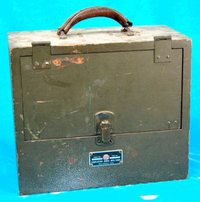
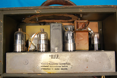
The BP2-A5 was housed in a simple plywood box painted the typical military olive drab color. The case was battered and dinged up but essentially sound and unbroken. See Figures 4 and 5 (see print version). Looking over the set, I found that work had been done on it. The original carrying handle had been replaced with a leather strap handle. A loop antenna was attached inside the case, as shown in Figure 6, and wired to the longwire antenna input. Also seen in the figure is the graying (actually green) on the chassis which, like many military items, had been coated with M.F.P. (Moisture Fungus Protection) varnish. The original battery plug was replaced with a different type. Also a small microswitch that switched off the filament battery when the front cover was closed had been added, as shown in Figure 7 (see print version).
There were several station log cards still inside the front cover. One side of the card had a typical station log entry form, and on the other side was a schematic diagram of the radio. The schematic was also silk screen printed on the inside of the radio back cover, as seen in Figure 8 (see print version). The schematic showed a representation of the battery plug, and it did not match the plug in the radio, so I knew that it had been replaced, probably to accommodate a different type of battery that was less expensive or easier to get.
When I found that the filaments in every tube were blown, I deduced that someone had probably miswired the battery, connecting the 90-volt B battery to the 1.5-volt filaments and burning them up. Still, the connector was wired correctly as found. The battery was housed in a separate compartment inside the cabinet and below the chassis. It must have been a real job to replace the battery. Ten screws must be removed to take the back of the radio off and access the battery. The ten screw holes can be seen in Figure 5 (see print version).
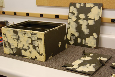
Figure 4. The case is a simple plywood box painted a military olive drab.Beginning the Restoration
The first thing I did was to remove the modifications. Whoever had installed the loop antenna did a really nice job. He did not cut or modify any of the original wiring, so I was able to restore it to original rather easily. He had mounted the antenna using four existing screws that were meant for the original metal carry handle.
To get more information on this radio I contacted a fellow member of the Tube Collectors of America, who is also a member of a military radio collectors' club. He got me in touch with Tom Laszynski, a military radio collector who has a BP2-A5 in his collection. Tom was an enormous help. He took several photographs showing the original handle and the control markers. He also had an original owner's manual, and he was kind enough to make photocopies of it for me. I found out from the manual that the radio was made for the British Ministry of Supply Mission through the U.S. Signal Corps in 1944.
Duplicating the Control Markers
The three control markers on the set were very unusual. I had one damaged original on the radio, seen in Figure 7 (see print version), lower right, and a photo showing what the others looked like. The manufacturer had used thumbtacks with a sort of paper overlay molded around the heads. The markings were printed on them indicating the function of the switch positions and then coated with a bright green clear coating. The tacks were pressed into the plywood front panel next to the control knobs. There was one labeled "OFF" next to the power switch/volume control. Two more were next to the band switch, one indicating "B" for the standard AM broadcast band and the other indicating "SW" for shortwave.
Figure 6. A loop antenna is attached inside the case.To duplicate these, I had to start from scratch and make a set of thumbtacks the size of the originals since they were a little bigger than the usual thumbtack size. I started by punching out 7/16" diameter slugs of thin mild steel on a Rotex shop punch. After that, I flattened the slugs and then drilled and countersunk the center dimple on each one. I inserted a small nail into the countersunk side and glued it in with a blob of epoxy. After the epoxy cured, I sanded the head smooth and flat, and then I rounded the edges by sanding them with a Dremel Moto tool. This got me to the point where I had a set of thumbtacks the proper size and shape.
Next, I spray painted the heads flat white to provide a neutral base for the final step. To get the heads the proper color and apply the markings, I used Photoshop Elements on the computer. Using a flatbed scanner, I scanned an image of the original tack into a digital image file. I sampled the color of the tack from that file and used the sample to paint the background in a new image.
I went through the available fonts and picked out one that was pretty close to the one on the existing tack. I typed the appropriate lettering and then, using the photo editor functions, I tweaked the lettering a bit to make it match in size and style. Now I had the lettering on the correct background color. I printed that image onto very thin tissue paper using a high quality color laser printer. (How I did that is an article in itself!)
I cut out the individual markings and glued them to the tack heads, wrapping the paper around the sides and twisting it tightly around the nail. After the glue was dry, I trimmed the excess paper off at the back edge of the head with a sharp knife. To finish the job, I sprayed the heads with several coats of clear high gloss acrylic to fix and protect the paper covering. The various steps of the process are shown in Figure 9.
Other Challenges
The plastic dial cover was split and needed to be replaced as shown in Figure 7 (see print version). I bought a kit from Dialcover.com and made a new one. I had never made a dial cover before. That took a little practice and experimentation, but I managed, and it turned out very nicely. (See A.R.C., December '09).
The carry handle was more of a challenge. The original handle was some hardware product that probably hadn't been manufactured for many years. Donna and I searched through flea markets, antique markets, and garage sales for something close, but we didn't find anything. I found one that was really close on a website for furniture hardware, so I ordered it. When I got the handle, it was not the same as shown in the picture on the website, but it would have to do. At least the screw hole footprint matched.
Figure 10. The chassis with several things to repair, but with a speaker cone in remarkably good condition.On the chassis as shown in Figure 10, I had the usual things to fix. Many of the paper capacitors were leaky and needed to be replaced. I gutted them out and rebuilt them with new Mylar capacitors inside. Although this is a lot more trouble than just replacing them, I prefer to try to keep the original look under the chassis if possible, while making the radio functional. I found that several carbon composition resistors were out of tolerance.
The volume control had been replaced with a huge one that barely fit under the chassis. The shaft was too short to attach the knob so there was no knob on it. Besides that, the control shaft was frozen. To match the other shafts, the original volume control would have had a plain shaft 1/4" in diameter with no flats and 1" long. My friend Dan Johnson looked through his junk box to see if he could find one like that. He found one with exactly the right shaft, with the right resistance, and with a switch attached to the back. (Some of you longtime readers might remember my July 1993 A.R.C. article about Dan Johnson's 1929 Kylectron electrostatic speaker.)
After replacing all the tubes, I powered the radio up on my bench power supplies, and it worked. I cleaned the band switches, went through alignment, and the electrical work was done. Now I had to deal with the cabinet.
Figure 14. The holes and dings are ready for sanding and paint.The Cabinet
Naturally, the cabinet was showing the years, and it needed some work. I removed the press fit, rusted steel feet from the bottom of the cabinet, (See Figure 11 in print version) and I bead-blasted them to remove the heavy coating of rust. The cabinet had extra holes drilled in it where the replacement handle (see Figure 12 in print version) and door switch were mounted. I filled the extra holes and dings with Elmer's Wood Filler, shown in Figure 13 (see print version) and 14. When it dried, I sanded it out smooth. With the holes and case damage filled, the cabinet was ready to paint.
To get the proper color, I took the front panel to a local paint store and had them scan it with their computerized color scanner. They mixed a quart of custom paint the same color as the original. I gave the cabinet two coats of paint using a small trim roller for the flat surfaces and a small artist's brush to get into the crevices. I asked a friend who has an airbrush to paint the new carrying handle for me.
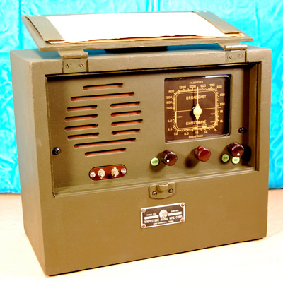
Figure 15. The finished product with the cover raised showing a station log card.After the paint was dry, I reassembled the cabinet and attached the various accessories, namely, the dial cover, carry handle, control markers, knobs and nameplate. Many of the original screws were missing, damaged, or badly rusted, so I replaced them.
Final Steps
Probably the most amount of work was invested in reprinting a copy of the owner's manual. This project could be another article on its own, but I'll describe the highlights. Tom Laszynski sent me a photocopy of the manual. He offered to scan it and send it to me in digital form, but I preferred a photocopy because they are very high resolution due to the analog nature of Xerography. The downside is that copied photographs tend to get a little muddy. I scanned the copies at very high resolution and imported them into my old workhorse Photoshop Elements.
Tom described some of the lettering in the manual as red and the cover as a grey lightweight card stock. I digitally restored each page and formatted the pages into booklet form saving the whole thing as an Adobe Acrobat multipage file. I printed the pages double-sided on a high quality laser printer, using grey cardstock for the cover. I stapled the prints together and folded them into booklet form.
Final Thoughts
Overall, I probably spent more time and money on this project than it is worth, but in the process, I had a lot of fun, and the results are shown in Figures 15, (16, 17 and 18 see print version).
I learned how to make plastic dial covers and there was enough material for three magazine articles. The practice I had fixing up the case was good experience. And the results were very satisfying.
I would like to offer a personal thanks to Tom Laszynski for all of the time he spent and for sending me the information that I needed for the project, and also to Dan Johnson for his help.
References:
Proceedings of the IRE, November 1944.
Templetone Model BP2-A5, Operator's Manual.
© October 2009 Daniel Schoo
Daniel Schoo, a frequent contributor to A.R.C., is an electronic design engineer with a lifetime interest in antique technology, especially radio and television equipment. In addition to his collection of 1930s and 1940s radios and video cassette recorders, he has a large collection of vintage vacuum tubes, neon lamps, and tube data books.
|
[Free Sample] [Books, etc., For Sale] [Subscribe to A.R.C./Renew] [Classified Ads] [Auction Prices] [Event Calendar] [Links] [Home] [Issue Archives] [Book Reviews] [Subscription Information] [A.R.C. FAQ]URL = http://www.antiqueradio.com/Feb10_Schoo_Templetone.html Copyright © 1996-2010 by John V. Terrey - For personal use only. Last revised: January 26, 2010. For Customer Assistance please contact ARC@antiqueradio.com or call (866) 371-0512 toll free Antique Radio Classified |