Of Old Radios And Related Items--Published Monthly
The Bremer-Tully Model 6-41
BY STEVE AUYER
WEB EDITION
Obey that inner voice that says, "Stop and look" whenever you pass that yard sale, especially if a radio is in view. That's Steve Auyer's lesson of the day as he describes his Bremer-Tully find. (Editor)
It was one of those days when you're driving along and not paying too much attention to the houses that you pass. You'll see something out of the corner of your eye and it doesn't immediately register, but your brain continues to process the information and pass on bits and pieces of data to you.
Brain: "That house we just passed had a yard sale."
Me: "Yeah."
Brain: "There was a radio in the driveway."
Me: "Yeah."
Brain: "It was kind of old-fashioned."
Me: "Oh?"
Brain: "It was one of those cabinets with the tall spindly legs."
Me: "Hold on while I make a U-turn."
The radio in question was a Bremer-Tully, a make that I wasn't all that familiar with. From a mechanical standpoint it looked to be in pretty good shape: speaker grill cloth torn, a few "dings" on the cabinet, back panel missing, and a few chips in the veneer. The price was right at $30, so I bought it.
After getting it home and checking it out, I uncovered a few electrical problems. The insulation on the line cord was cracking off, the tuning capacitor shorted out over part of its rotation, and the volume control was erratic. The filter capacitors in the power supply were paper units and still in good condition, and the other electrical parts were functional.
A little research showed that the set was a Bremer-Tully Model 6-41, which sold for $190 in 1928. There was also a Model 6-40, which was a tabletop set. Alan Douglas presents a good overview of Bremer-Tully and its product line on pages 90-95 of his book Radio Manufacturers of the 1920's Volume 1.
Circuitry
From an electrical design standpoint, the circuitry is pretty simple, as shown in Figure 1. With filament voltages of 1.5, 2.5 and 5.0 volts, and three different B+ voltages, the power supply has to provide a number of outputs. There's an untuned RF amplifier stage, two tuned RF amplifier stages, a detector, AF amplifier and output stage. With that kind of RF circuitry, you'd expect good sensitivity but not great selectivity, and that's just what the set demonstrated.
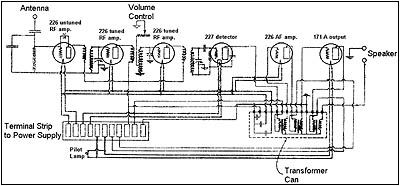
Figure 1. A schematic diagram for the Bremer-Tully shows a typical 6-tube TRF set with an untuned 1st RF stage.
The volume control is simply a rheostat that shorts out the secondary of one of the IF transformers. Also, with a single-ended 171-A output, you'll get less than a watt of audio output, but the set's tone quality was surprisingly good. We'll see why in a bit.
Construction
Bremer-Tully had a reputation for good construction quality, and this set shows that. The set is well laid out and nicely built. The shorting problem with the tuning capacitor was due to the fact that the three stator sections mount to fiber panels, which, slightly deformed with age, allowed the rotor and stator plates to come into contact. But Bremer-Tully designed its tuning capacitor with three individual rotor sections that lock to a common shaft with set screws. So loosening the set screws allowed the rotor sections to be adjusted to eliminate the shorting problem.
Figure 2 (see print version) shows how the set is constructed with two separate chassis -- one for the radio and one for the power supply. Both chassis mount to a base panel, which slides into the cabinet and locks in place with two screws. The chassis are painted a light shade of purple -- don't ask why. The paint was applied after the chassis were assembled, as there are several hard-to-reach areas that were left unpainted.
Restoration of the cabinet included stripping the original finish, repairing the veneer in a few areas, fabricating a back cover, replacing the grill cloth, and refinishing the cabinet. Figure 3 shows the completed unit. Remember that this was a late 1920s radio, and the upper end of the tuning range is 1520 Kc. Figure 4 (see print version) shows a closeup of the simple, but rather elegant control panel.
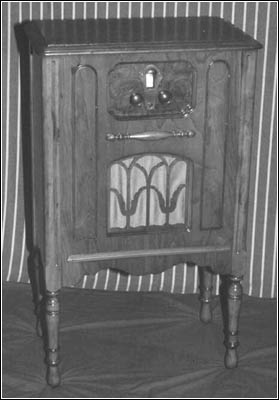
Figure 3. The restored cabinet gives this radio that "fresh-from-the-factory" look.
Loudspeaker Design
Figure 5 (see print version) shows a back view of the cabinet with the cover removed. Ordinarily one would expect to see a loudspeaker in the space beneath the radio chassis, but, in this case, what is seen is a wooden enclosure, about 8" square and 6" deep. As shown in Figure 6, this enclosure contains an 8" Peerless speaker, an electrical network in the lower right-hand corner, and a removable back consisting of a 1" thick pad of dense fiber (probably horsehair). Why the network and the fiber back? Let's digress into loudspeaker design for a moment.
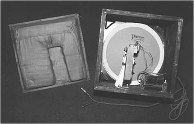
Figure 6. The speaker system used acoustical padding and a low-pass filter to improve its low frequency response.
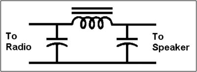
Figure 7. This schematic shows Bremer-Tully's solution to enhance its speaker's low frequency response, which is a classic low-pass filter design.
Early radios used horn-type speakers. Because of the size of these units, they began to be replaced with cone-type speakers in the late 1920s. But the early cone-type speakers differed from today's speakers that use a voice coil to drive the cone. Early cone-type speakers had a coil of wire that induced a varying magnetic field in an iron vane. The iron vane was in the field of a permanent magnet and thus would vibrate in step with the applied signal. The movement of the iron vane was coupled to the speaker's cone through a stiff piece of wire.
Compared to today's speakers, these early units were much higher in impedance. Typically the coils had a DC resistance of from several hundred to several thousand ohms. Their low frequency response was also poorer. The limit of a speaker's low frequency response is set by the frequency at which the mass of its cone and the stiffness of its suspension are mechanically resonant. These early speakers typically had a low frequency limit of several hundred Hz -- compared to 20-40 Hz for today's speakers.
So the Bremer-Tully's designers were faced with the dual problems of fairly low audio power to drive the loudspeaker, and the poor low frequency response of the speaker. Thus, the network and the fiber back.
The purpose of the fiber back on the speaker enclosure is to allow low frequencies to pass from the speaker enclosure into the radio's cabinet while absorbing or attenuating the high frequencies. The effect of this is to improve the speaker's efficiency at low frequencies.
Electrical Network
Examining the electrical network in the speaker enclosure, we found a pi-network, low pass filter consisting of a single iron-core inductor and two paper capacitors. The network is a classic low-pass filter (see Figure 7). Thus, the Bremer-Tully's designers chose a quality speaker to begin with, added features to improve its low frequency response, and an electrical network to attenuate some of the higher frequencies.
The net result is shown in Figure 8, which plots the electrical impedance of the set's speaker as mounted in the cabinet, and takes into account the effects of the electrical network and low frequency matching technique. At low frequencies the impedance is close to the 1600 ohms DC resistance of the speaker's driving coil. The impedance rises with frequency, showing a "wiggle" (see Figure 8), around 200 Hz which represents the mechanical resonance of the speaker's suspension. The impedance continues to rise, peaking at about 14,000 ohms at 600 Hz and then beginning to fall.
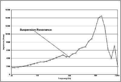
Figure 8. Chart showing the frequency vs. impedance suspension resonance "wiggle" around 200 Hz.
While an impedance range of 4,000 ohms to 14,000 ohms looks like a lot, it really represents about a 2 to 1 swing from a mean value, and one into which the radio could deliver power. This gives the Bremer-Tully a frequency response of from 200 Hz to about 5 kHz -- not great by today's standards, but one that produced a very nice-sounding radio in the late 1920s with a minimum of parts!
Reference:
Douglas, Alan. Radio Manufacturers of the 1920's. New York: Vestal Press, Ltd., 1988.
(Steve Auyer, 3925 Cloverfield Circle, Liverpool, NY 13090)
Steve Auyer has been interested in the historical aspects of radio ever since he toured the WLW 500 KW transmitter site in 1963. Lately his interests have turned to researching and documenting local AM broadcasting history. Recently retired from Lockheed Martin, he also spends his time coordinating the Amateur Radio exhibit at the Museum of Science & Technology in Syracuse, New York.
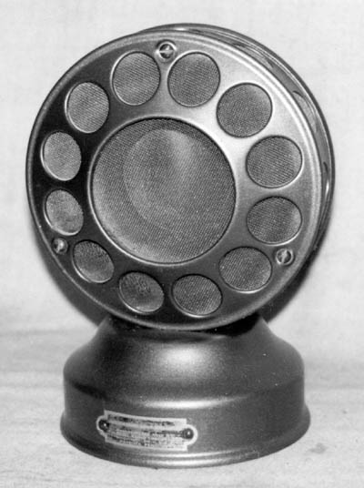
Figure 9. The Kodel "Microphone" speaker.
| [Free Sample] [Books, etc., For Sale] [Subscribe to A.R.C./Renew] [Classified Ads] [Auction Prices] [Event Calendar] [Links] [Home] [Issue Archives] [Book Reviews] [Subscription Information] [A.R.C. FAQ] URL = http://www.antiqueradio.com/Jan03_Auyer_BremerTully.html Copyright © 1996-2002 by John V. Terrey - For personal use only. Last revised: December 10, 2002. For Customer Assistance please contact ARC@antiqueradio.com or call (866) 371-0512 Pages designed/maintained by Wayward Fluffy Publications
Antique Radio Classified |