
Of Old Radios And Related Items--Published Monthly
Cabin Fever--A high-performance crystal set
BY ALAN DOUGLAS
WEB EDITION
We all know that "real radios glow in the dark," but in this article, Alan Douglas describes a "real radio" that doesn't. His home-brew crystal set is an excellent performer. (Editor)
It all started last February, when a notice appeared in the "Radio Classified" section of the Antique Radio Forum offering sound-powered headphone elements. I'd used antique Baldwin and Western Electric phones for years, with various home-brew or commercial crystal sets, but had never come across sound-powered phones which were reputed to be even more sensitive. And I hadn't done any broadcast-band DXing on a crystal set in a very long time.
Since the seller had a Crosley 50 with a wrong tuning coil, and I had a bare spiderweb form, which I could rewind to a pretty close match, I swapped the rewound coil for a pair of sound-powered elements, originally -- so I was told -- from Mississippi tugboats. Apparently these phones are still used on boats as absolute backups when all power fails.
The phones arrived and did seem much more sensitive than my Western Electric 509W headset when tested on an audio signal generator. They were a little too large to fit any of my cushioned headsets, but I found a junker pair of cheap phones whose headband was just the right size to grip the sound-powered elements when I drilled a couple of depressions in the plastic housings.
At the February Westford Greater Boston Antique Radio Club (GBARC) Radio XXXIV show, organized by A.R.C. (gotta get that plug in), I picked up a copy of "Crystal Radio Bonanza" which is three years' worth of newsletters of the Xtal Set Society. In there, was a description of Mike Tuggle's "Lyonodyne" crystal set, with which he has snagged many mainland broadcasters from his Hawaiian location. I remember buying some Q-meter coils from Mike just before he moved, when he was lightening his load.
Mike's design is a double-tuned, loose-coupled one, using tuned circuits separately mounted on boards and physically moved around the table top to vary the coupling. I've always liked loose-coupled designs, and I thought, why not try building one to go with my new headphones?
It's an admission of defeat to actually buy anything for a project like this, so I began rooting through the junk box -- a.k.a. my cellar -- for suitable parts. Mike used high-quality tuning capacitors and litz-wire coils, which I couldn't duplicate, but I did find a lab-grade 0.001mF capacitor made by Muirhead in England, in a heavy brass case with ceramic insulation, which I recall buying from a local Ham thirty years ago. I also found a new spool of 50 x 38 litz wire that I must have bought at a radio meet at some point. For the 2-gang, antenna-tuning capacitor, I came up with a 1928-vintage Camfield made in Chicago. I think Camfield sold superhet kits.
Arranging these parts and a couple of odd coils on the bench, connected by clip leads, and using the antenna I first put up around 1960, I was rewarded with sounds from the phones, so it was time to make something decent looking. A little cut-and-try (I had to splice in two extra turns) with the litz wire on a rolledup sheet of heavy Mylar got me a coil that tuned down to exactly 530 kHz with the 0.001mF capacitor. One of the odd coils from the junk box, an old one wound with green silk-covered wire, tuned just right as the antenna coil. To get down to 530 kHz I had to cut out the series-tuned gang, accounting for the two "ground" posts shown on the schematic in Figure 1. I use whichever gives the louder signal.
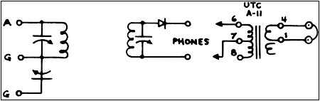
Figure 1. The schematic diagram for the crystal set shows the antenna tuner on the left. Note the two ground connections. Their use is explained in the text. The tuner/detector is shown at the center and the outboard audio matching transformer and headset connection are shown on the right. One winding of the transformer is not used.
What's the saying: "If you steal from one person it's plagiarism, but if you steal from many, it's research." I did some internet research. Ben Tongue, as in Blonder-Tongue Labs, in particular has some advanced engineering data on his site. I cribbed the idea of using a selected germanium diode connected to the hot end of the secondary tuner, feeding a high-quality stepdown transformer to drive the low-impedance phones. By some fluke, I had the recommended UTC A-11 transformer; one of its windings was open despite its being new in the box, but I didn't need it anyway. [The UTC A-11 is a line to grid audio matching transformer with a 50 KOhm secondary and primary connections of 50, 200 and 500 ohms. In this application, the transformer is used as a step-down transformer.]
There is endless discussion of which detector is best, but I found by trying some germanium diodes that a 1N198 worked well. Following one of Ben's suggestions, I tried heating and cooling it and found it was optimum at room temperature, showing that its operating point is well suited to the high-impedance transformer load it was feeding.
One can try to optimize the antenna, the circuit, the coil Q, the detector, the headphones, or any combination of these. And for those who enter contests, persistence and luck play a large part too. I chose not to worry about the detector, nor to buy any $100-a-spool, hundreds-of-strands litz wire. And I already have a good antenna, an inverted-L about 25 feet up, from the house to the barn. My ground is a 2" well pipe in the cellar, 20 feet long, 12 feet below the water table (it hasn't been used as a well for at least fifty years).
Since it appealed to me to make this set look properly antique, I used black-anodized aluminum panels, Eby binding posts, bus-bar wiring, and a National type A vernier for the main tuner. I did have to disassemble the National and grease some moving parts, but it tunes really smoothly. Since the Muirhead capacitor is straight-line capacitance, the top end of the broadcast band is extremely crowded, so I wound another litz coil with half the number of turns to cover that range. The "top end" coil then works fine as the antenna tuner, in place of the large green-silk coil which won't get past 1500 kHz. For reference, the coils are 3" diameter; 15, 30 and 42 turns; 20, 72 and 180 microhenries. The finished crystal set is shown in Figures 2 and 3.
As for performance, this set easily has 10 kHz selectivity. Luckily, my nearest 50 KW stations are 70 miles away, and they only bother the immediately-adjacent channels. I was able in about a week of casual listening in early March to log stations on 60 out of the possible 70 channels from 530 kHz to 1220 kHz. The set will tune higher, but waiting for puddle-jumper stations to fade in and out is tedious.
My best DX from Cape Cod, Massachusetts, would be WIOD Miami, Havana on 640, and the South Caicos Islands station on 530 kHz. Some stations, of course, have been heard only on one night, when propagation is good, It is after all only a crystal set, with no amplification. For making my initial calibration, I used a Sangean DT200V pocket radio (a marvelous performer on both AM and FM!) to verify what channel I was tuned to, but the type A vernier is resettable to any frequency with no ambiguity.
For further information, I recommend starting with the references at Ben Tongue's site: http://uweb.superlink.net/bhtongue/index.html or search for "crystal set" and follow the links.
(Alan Douglas, Box 225, Pocasset, MA 02559)
Alan Douglas, an electrical engineer, has written over 100 articles for A.R.C. and other publications. His books "Radio Manufacturers of the 1920's," Vols. 1, 2, and 3, are highly regarded resources for the radio-collecting community.
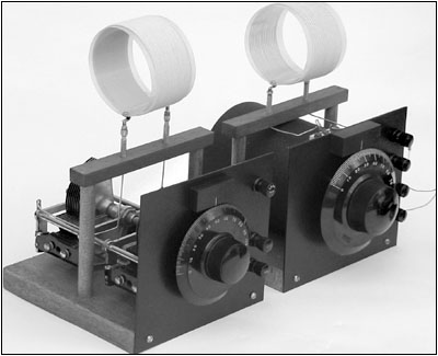
Figure 2. The two finished, home-brew units: the main tuner is shown at the right. The 2-gang variable capacitor can be seen in the antenna tuner on the left.
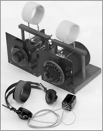
Figure 3. The complete crystal set with the outboard audio-matching transformer.
�
| [Free Sample] [Books, etc., For Sale] [Subscribe to A.R.C./Renew] [Classified Ads] [Auction Prices] [Event Calendar] [Links] [Home] [Issue Archives] [Book Reviews] [Subscription Information] [A.R.C. FAQ] URL = http://www.antiqueradio.com/Jan04_Douglas_CabinFever.html Copyright © 1996-2003 by John V. Terrey - For personal use only. Last revised: December 26, 2003. For Customer Assistance please contact ARC@antiqueradio.com or call (866) 371-0512 Pages designed/maintained by Wayward Fluffy Publications
Antique Radio Classified |