
Of Old Radios And Related Items--Published Monthly
Restoring an Early Coast Guard Transmitter
By Ray Bintliff, W1RY
WEB EDITION
Radios in need of restoration frequently have a few hidden problems. Ray describes a basket case in which a number of problems were uncovered as the restoration progressed. It was necessary to replace or replicate missing parts in order to restore the set to its original condition. However, the finished product was well worth the effort.
The restoration was made easier by the loan of an unmodified transmitter by the late Alton DuBois. He had both a transmitter and the matching receiver in his collection which he described in an article in the January 2003 issue of A.R.C. The article offers a prime example of the willingness of fellow collectors to help one another. (Editor)
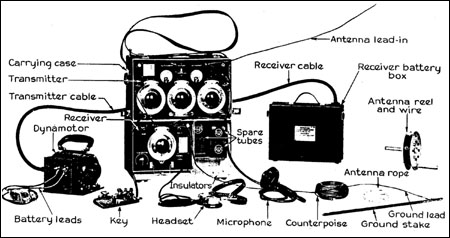
It all began at a New England Antique Radio Club swap meet when Bill Holly, a long-time Ham and collector from Maine, asked me about restoring a 1931 Coast Guard transmitter manufactured by General Electric. We learned later that it is one of the units that make up the Coast Guard Portable Radio Station, Model T-22/CGR-22. Its GE designation is Type RT-80A. The complete station is shown in Figure 1. Powered by a battery box and dynamotor, the station is capable of CW or voice communication over the frequency range of 2,464 to 4,050 kHz.
Figure 1. The transmitter described in this article is part of the Coast Guard Portable Radio Station shown here with its accessories.THE TRANSMITTER
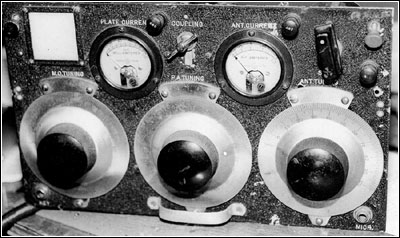
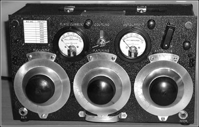
A front view of the transmitter in its as-found condition is shown in Figure 2. The transmitter, a Master Oscillator Power Amplifier (MOPA) design, uses four Type 112-A tubes: one as an oscillator, another as an RF amplifier, and a pair as the push-pull modulator stage. The front panel controls include three tuning dials used to adjust the master oscillator tuning, power amplifier tuning and antenna tuning. The two meters display plate current and antenna current. The bar-shaped knob operates the send/receive switch. The control at the top center adjusts the antenna coupling coil.
The key jack is located at the left bottom corner of the front panel and the carbon microphone jack is at the far right. The three binding posts, from left to right, are for the Ground, Antenna and Receive connections. The ground post is isolated from the chassis ground and connects to an earth ground. The receive binding post is used to connect the antenna to the receiver's antenna post when the station is in the Receive mode.
A CAVEAT & THE REALITY
Bill warned me that the transmitter had suffered some "modifications" by a previous owner and that the restoration might not be an easy task. The set looked interesting and I carried it home -- full of hope.
Figure 2. A front view of Bill Holly's transmitter that shows its as-found state.As I examined the set on the workbench, the extent of the modifications became painfully clear. It looked as if we were headed for a resurrection rather than a restoration.
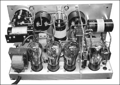
Figure 3 (see print version) shows a rear view of the transmitter in its as-found state. Restoration needs ranged from the simple, such as missing tubes, to the major, such as wiring, coils and components.
Turns of wire had been removed from two of the tuning coils and one coil was missing. Further inspection revealed that a crystal socket had been added to the oscillator stage and some bus-bar wiring had been cut. Later in the restoration effort, I discovered that a trimmer capacitor had been removed as well.
The more I looked, the more problems I found. The send/receive switch on the far left had been rewired and the RF current meter had a jumper across its terminals. More missing parts and modifications were discovered as the restoration progressed.
Underneath the chassis, things were not quite as bad. As Figure 4 shows (see print version), one of the original Aerovox can-type capacitors had been replaced with a more modern capacitor. Some wiring changes were noted at the capacitors' terminals and the microphone jack. Also, a jumper had been wired across the terminals of the wire-wound resistor at the bottom right of the photo. Note the generous use of asbestos insulation around the three carbon resistors.
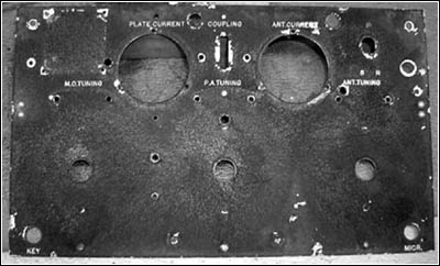
Figure 5. The front panel has been removed and ready for stripping and repair. Extra holes, dings, scratches, and grime all added up to one nasty looking panel.
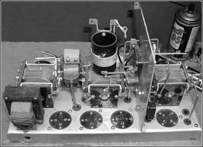
Figure 6. In this rear view, disassembly of the transmitter is underway. The front panel has been removed. The modulation transformer is located in the lower left corner and the microphone transformer is in the upper left next to the variable capacitor.The transmitter's aluminum front panel and cabinet were in poor cosmetic condition because of aged and dirty paint, dents and scratches. Also, a number of non-original holes were drilled in the panel and cabinet. Figure 5 shows the condition of the front panel.
WHERE DO WE GO FROM HERE?
Before any serious restoration effort could be performed it was necessary to determine the set's original configuration. Without a schematic diagram or coil winding data, the prospects for an authentic restoration seemed dim. But radio collectors, being a tenacious and closely-knit bunch, always seem to find solutions. Fortunately, Bill had obtained some photocopies of data for the transmitter. The not-so-good news was that the illustrations were of marginal quality and a schematic was not included.
Then Bill learned that the late "Andy" Dubois had an unmodified transmitter and receiver in his collection. Andy offered the loan of his transmitter to assist the restoration project. Without his help it is unlikely that the restoration could have been accomplished. Andy will be remembered as a frequent contributor to A.R.C. He wrote about his transmitter and receiver in the January 2003 issue of A.R.C.
Using Andy's set as the model, I began counting coil turns, checking for more missing components and tracing the set's wiring. At this point, a "first cut" schematic diagram was prepared and it was time to begin the actual restoration.
READY TO RESTORE
As a first step, all of the components mounted on the front panel were removed. Then the panel was removed so that it could be stripped and repainted. Removing the panel had a side benefit -- it made it easier to reach some of the chassis-mounted components. Figure 6 shows one stage in the disassembly process.
After the panel was stripped of its paint, an engraver's error was discovered in the upper left corner of the panel. As Figure 7 shows (see print version), the legend for the plate current meter was misplaced and engraved again in the correct position. GE solved the problem by simply painting over the incorrect engraving. Ain't black wrinkle paint a wonderful cover up!
The antenna loading coil was missing from Bill's set. So, a replacement was replicated using old parts and materials. The other three coils were cleaned, their old windings removed and then rewound using double cotton covered wire. The set of rewound coils is shown in Figure 8 (see print version).
THE HOME STRETCH
After the chassis and components were cleaned and the tuning capacitors were lubricated, it was time to reassemble the set. Replacements for missing mica and trimmer capacitors were found. The missing bathtub capacitor was recreated, complete with a label. Wiring modifications were returned to their original state and things were starting to look good. Alas, it was too good to be true. Remember that jumper across the RF ammeter? It was there because the meter was open. So the search for a suitable thermocouple ammeter began.
Figure 10. A front view of the restored transmitter with that just-from- the-factory look.At this point, a brief and simplified explanation of how a thermocouple ammeter works may be helpful. A thermocouple type ammeter consists of the usual DC meter movement connected to a thermocouple. A thermocouple is a junction of two dissimilar metals that produces a DC voltage when it is heated. If that heat is generated by the flow of RF current then a DC voltage is generated that causes a deflection in the meter movement and we get a measurement of RF current. Thermocouple meters were "big stuff" long ago and they were used in transmitters of World War II vintage. They are not as plentiful today and finding one in working condition is difficult. The chance of finding an identical meter to replace the bad one borders on the impossible.
The only practical solution was to keep the meter with its DC movement and replace its thermocouple. Hey, that's duck soup. Right? Not really. After buying, begging and borrowing a bunch of ammeters as possible sources of a good thermocouple, I was unable to find one in working condition. Finally, a friend came to the rescue with a meter that contained the sealed-in-glass thermocouple shown in Figure 9 (see print version).
Every problem may have a solution, but sometimes it seems that every solution has a problem. After removing the thermocouple from its meter case and hooking it up to the old meter, it worked just fine. But, it was too big to fit in the old meter case. I decided to mount the thermocouple outboard and hide it behind the meter. With all of the electronics ready to go it was time to mount the meters, dials and such on the front panel. Before we get into that let's touch on the repainting work.
REPAINTING
As mentioned previously, the cabinet and front panel were in poor shape. So, the first task was to strip the paint from both pieces. Next, the extra holes, gouges and dents were repaired using autobody filler followed by a light sanding.
Painting was done with a spray can of black wrinkle paint, and painting the cabinet was easy enough, However, the front panel presented a problem. At the factory, the panel was painted first and then engraved. Now the panel was engraved and the problem was how to keep the new paint job out of the engraved lettering. Several approaches were considered including filling the engraving with soft wax and removing it after the spray painting was completed. In the end, the simplest and best method was to scrape out the paint from the engraving using a scribe. This operation had to be repeated after each layer of paint was applied. The work was difficult and time- consuming, but it produced a shiny engraving that contrasted with the black wrinkle finish.
THE END IS NEAR
Figure 11. A rear view of the restored transmitter with all components and tubes in place.The last cosmetic task was to polish the nickel-plated dials and hardware. Then all front panel components were mounted and electrical connections made. A dummy load was installed at the transmitter's output connections, and now it was time for the smoke test.
There was no smoke and the lamps in the dummy load glowed nicely. The restoration was complete and the little rig worked. Tuning up the transmitter is a little tricky and requires two hands because of the interaction between the oscillator and amplifier tuning controls.
THE FINISHED PRODUCT
Two views of the restored transmitter are shown in Figures 10 and 11. A reproduction of the set's nameplate is shown in Figure 12 (see print version). The schematic diagram that appears in Figure 13 (see print version) and the parts list shown in Table I were generated as part of the restoration effort.
Although there were some frustrating moments, it was very satisfying to see the abused transmitter restored and operating again.
In closing, I would like to cite again Andy DuBois' contribution to the success of this restoration.
(Ray Bintliff, W1RY, 2 Powder Horn Ln., Acton, MA 01720)
Ray Bintliff, W1RY, a member of the A.R.C. editorial staff, holds an Amateur Extra Class license. In addition to Amateur radio, his interests include electronic equipment design and audio reproduction. He also enjoys repairing and restoring pre-1945 radios and test equipment.
Table I. Parts List and Reference Designators for the Coast Guard Transmitter
Table I PARTS LIST
U.S. COAST GUARD TRANSMITTER MODEL T-22Ref. Desig. Part Description C1, C5, C9 0.0005 mF, mica capacitor C2 Trimmer capacitor, band set C3 Variable capacitor, (M. O. TUNING) C4 0.01 mF, mica capacitor C6 Trimmer capacitor, neutralizing C7 0.005 mF, mica capacitor C8 Variable capacitor, (P.A. TUNING) C10 Variable capacitor, (ANT. TUNING) C11, C12 1.0 mF, can-type paper capacitor J1 Jack, (KEY) J2 Jack, (MICR.) L1 See X1 L2 Coil, (M. O.) L3 See X2 L4 Coil, (P.A.) Ref. Desig. Part Description L5 Coil, (COUPLING) L6 See X3 L7 Coil, Antenna M1 Meter, RF ammeter, 0-1.5 A M2 Meter, DC ammeter, 0-100 mA R1 Resistor, carbon, 15k, 2w R2 Resistor, wire-wound, 0.8 Ohms R3 Resistor, carbon, 10k, 2w R4 Resistor, carbon, 5k, 2w R5 Resistor, wire-wound, 3.5k R6, R7 Resistor, carbon, 1.0 meg, 1/2 w T1 Transformer, modulation T2 Transformer, microphone input VT1-VT4 Vacuum tube, Type 112-A X1, X2, X3 Choke, RF
| [Free Sample] [Books, etc., For Sale] [Subscribe to A.R.C./Renew] [Classified Ads] [Auction Prices] [Event Calendar] [Links] [Home] [Issue Archives] [Book Reviews] [Subscription Information] [A.R.C. FAQ] URL = http://www.antiqueradio.com/Jul04_Bintliff_Coastguard.html Copyright © 1996-2004 by John V. Terrey - For personal use only. Last revised: June 24, 2004. For Customer Assistance please contact ARC@antiqueradio.com or call (866) 371-0512 Pages designed/maintained by Wayward Fluffy Publications
Antique Radio Classified |