Of Old Radios And Related Items--Published Monthly
Having Fun with the Crosley Model 50
BY ROBERT B. ENEMARK
Web Edition
Here, Robert Enemark writes about an early battery set, the 1-tube, Crosley Model 50. By adding a battery box, an interface for modern, low-impedance phones, and an amplified speaker option, he has made the old Model 50 into a convenient set to display and operate. (Editor)
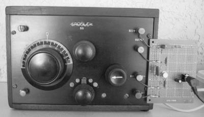
The Crosley Model 50 1-tube regenerative receiver, shown in Figure 1, was introduced in 1925. The circuitry was licensed for manufacture under Armstrong's patent #1,113,149, (experimental and Ham use). It is probably the simplest such circuit that works and operates nicely. It uses a single Type 01-A tube, requires both 6-volt and 22.5-volt batteries, and drives high impedance headphones.
Figure 1. The familiar Crosley Model 50 1-tube receiver of 1925, with the emitter-follower unit I constructed attached.Interesting Features
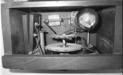
This little radio has several interesting features. The tuning capacitor is a "book-type" in that two molded "mud" plates covered with conducting foil are hinged together on one side and kept open with a spring. Between these plates is a large mica sheet for insulation and increased dielectric factor. One plate is fixed while the other can be closed, like a book, by turning the large front dial which rotates a cam to close that plate against the other. See Figure 2.
The input circuit is series tuned via the antenna connection. Since most antennas of reasonable length and insulated, have more capacitance to ground than the book condenser, there is less circuit detuning due to the antenna.
At any rate, a selector switch on the front panel has four settings to change the inductance of the grid input coil to provide a fairly wide range for the BC and lower SW frequencies. Both the grid and plate coils are "spider-wound," and the coupling between the two is adjusted by a push-pull action using the front panel regeneration control knob. Instead, most sets either rotate the feedback coil, or use a fixed coil together with other means to vary the circuit gain.
Figure 2. Looking down into the interior of the Crosley Model 50, showing the patented book-type tuning condenser and the operating cam shaft at the left.The Crosley Circuit
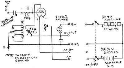
The simple Crosley Model 50 circuit is shown in Figure 3. Granted, even with the high-impedance phones, the volume is low for distant stations unless a really long antenna is used. Also, a good ground seems to be necessary to tame extraneous feedback.
A battery box, its schematic also shown in Figure 3, was made using a flat, plastic container with a lid. Three 9-volt radio batteries were connected in series for a 27-volt plate supply, which should last
indefinitely as the plate current is only a milliampere or two. However, the Type 01-A tube filament draws 1/4 ampere at 5 volts, so the use of four D-cell batteries will last about the same as in a flashlight. A D-cell holder can be purchased from a parts store like Radio Shack.
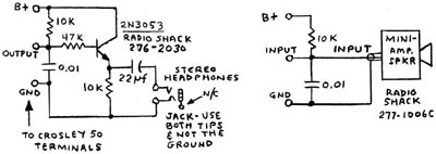
High-impedance phones, such as Murdock or other older manufacturers, are usually quite heavy and bulky, whereas small, modern "stereo" phones are comfortable but do not work because they are of low-impedance. A simple interface can be made for these low-impedance phones using an emitter-follower stage with close to unity gain, as seen in Figure 4.
The Model 50 plate voltage is around 15, so the emitter follower draws less than 2 milliamperes on the average. The 0.01 microfarad by-pass capacitor is placed in parallel with the one in the Crosley to lessen feedback problems. Note the connections for the stereo headphones are made to the tip and ring lugs of the headphone socket, with the sleeve lug unused. See Figure 4. This saves buying a stereo-to-monaural plug adapter.
Figure 3. The Crosley Model 50 circuit diagram at the left, and the home-built battery box circuit at the right.Also shown in Figure 4 are the connections to a Radio Shack mini-amplifier/speaker unit #277-1008C, ($12). This is the easiest way to get some additional gain, and headphones also may be plugged into it if desired. This amplifier/speaker unit requires a separate 9-volt radio battery.
Operating the Receiver
Operating the receiver takes a little patience, as it does with most regenerative sets. With an antenna and ground connected, push the regeneration control knob all the way in for minimum feedback.
Start with the coil switch at position 4 for the lowest frequencies, and leave the filament rheostat at its lowest, CCW, and the tuning control dial at 100. Turn on the power and advance the rheostat unit until there is background noise, or reduce it if there is a squealing sound.
Tune for a station and adjust the feedback for best audio, just under oscillation point. Note that feedback increases somewhat as the tuning frequency increases, (dial numbers decreasing). Change the coil selector switch to reach more stations. A little experimentation with the tuning dial and selector switch and logging settings will aid in getting back to desired stations.
This set can pick up weak stations almost as well as a modern superhet, albeit with more fussy tweaking here and there. The Crosley Model 50 is a fun set to operate, and it is interesting to see how so few components can do such a good job.
Reference: Dave Crocker, Mashpee, MA
(Robert B. Enemark, P. O. Box 1607, Duxbury, MA 02331)
Figure 4. The emitter-follower impedance transformer diagram for low impedance headphones at the left, and an alternative circuit with volume gain at the right.
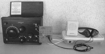
Figure 5. The complete set-up I used to operate the Crosley Model 50. To the far right is the plastic battery box. The mini-amplifier/speaker from Radio Shack is above the battery box and the emitter-follower allowing the use of low-impedance phones is attached to the right of the Model 50.Robert B. Enemark has been a Ham operator since 1941 with calls W1NLL and W1EC. He has been collecting antique radios since 1982, particularly pre-World War II shortwave sets and telegraph equipment. In 1980, in Duxbury, Mass., he set up a museum display of early French ocean cable telegraph equipment, which he had restored to working condition.
His career spanned World War II radio/radar service in the Marine Corps. to working as a consulting engineer specializing in VLF submarine reception, radar countermeasures, military weapons testing, industrial instrumentation, and photo-electric smoke detectors. He holds over 50 U.S. and foreign patents.
�
| [Free Sample] [Books, etc., For Sale] [Subscribe to A.R.C./Renew] [Classified Ads] [Auction Prices] [Event Calendar] [Links] [Home] [Issue Archives] [Book Reviews] [Subscription Information] [A.R.C. FAQ] URL = http://www.antiqueradio.com/Jun04_Enemark_Crossley50.html Copyright © 1996-2004 by John V. Terrey - For personal use only. Last revised: May 31, 2004. For Customer Assistance please contact ARC@antiqueradio.com or call (866) 371-0512 Pages designed/maintained by Wayward Fluffy Publications
Antique Radio Classified |