Of Old Radios And Related Items--Published Monthly
A Universal Driver for
Orphan Speaker HornsBy Philip Bliss
Web Edition
Here is a novel approach to constructing replacement bases and drivers for horn speakers using readily available parts. (Editor)
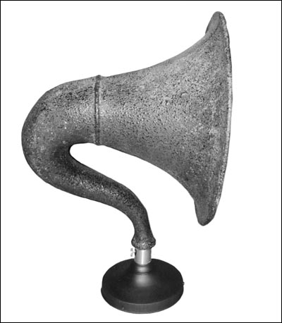
During the past few years I have purchased several horn speakers that were missing drivers or bases. In each case, I constructed a replacement. However, each one was somewhat different in terms of shape and size. I recently acquired a Baldwin horn, which was missing the base, and of course the driver. After checking it over, I noted that the driver end of the horn was about 3/4" in diameter about the same size as other horns that need driver assemblies. This being the case, I set out to design and build a base and driver that would fit a wide range of horns and would be both functional and attractive. The result of my efforts is shown in Figure 1.
To meet this goal, my requirements included construction materials that were readily available and did not require the use of special tools.
Materials
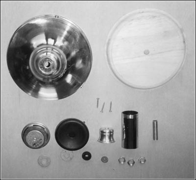
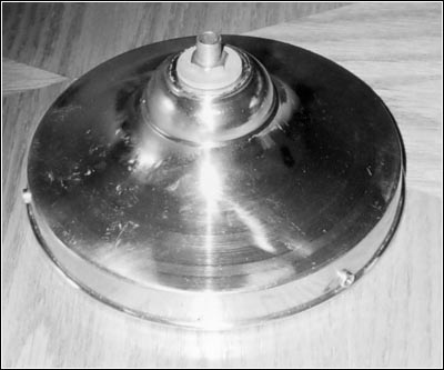
On a trip to an electric lamp store, I was able to purchase all of the parts necessary to make a base assembly. I used a holder for glass shades as the base, shown in Figure 2. This holder is 6" in diameter and 21/2" high; its shape is similar to several units shown in Floyd Paul's horn speaker books. (Similar shade holders are available in a number of diameters ranging from 41/2" to 8".)
I added a wooden lamp base to the shade holder to complete the base. The wooden lamp base is 6" in diameter and 3/4" thick.
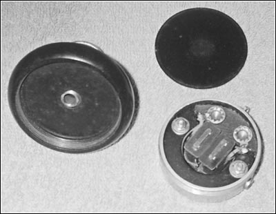
Shown in Figure 2 is another readily available part, a threaded candle holder. Lamp shops will usually call it a cup for lamp sockets or candles, The cup is used to hold the neck of a horn. The opening of the candle holder is 7/8" in diameter and about 1" deep. These dimensions will accommodate the driver end of many horns such as Magnavox, Baldwin, etc.
Figure 1. The completed driver base shown with the Baldwin horn.
Figure 2. Shown are the parts required to construct the universal base and driver unit. Clockwise from the top: a holder for glass shades, a wooden lamp base, a threaded pipe nipple, a chrome-plated sink drain pipe, and a lamp candle cup along with the screws, nuts and washers. Two examples of a driver are shown below the shade holder.
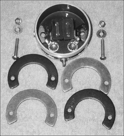
Figure 3. The extra magnets and hardware needed to modify the Federal earphone.The other parts needed to complete the horn base are: a 1/8-IP pipe nipple, 11/2" long; three 1/8-IP nuts; two 3/8" O.D. flat washers; three #4 wood screws, 1" long; and a length of 11/4" chrome-plated, brass sink drain pipe.
The Driver
I modified a Federal 53-W earphone for use as the driver. The first operation was to double the number of magnets in the earphone. To do this I had to cannibalize the other earphone from the set and use longer screws to hold the magnets in place. Figure 3 shows the extra magnetic and longer machine screws used to modify the earphone. Figure 4 (see print version) shows the modified earphone.
Next, I used JB Weld to glue the pipe nipple to the earpiece of the earphone, as shown in Figure 5 (see print version). I had to be very careful in positioning the nipple so that it did not come in contact with the driver's diaphragm. The purpose of the nipple is twofold: first, it is used to transmit sound from the base-mounted driver to the candle holder; second, along with the washers and nuts, it secures the driver to the base. When the JB Weld had cured, I assembled the earphone and tested it to make certain the diaphragm was not striking the nipple.
Assembling the Driver and Base
I then installed two of the nuts and a flat washer on the nipple and adjusted the top nut for proper clearance between the driver and the shade holder. Next, I used the bottom nut as a lock nut. Figure 6 shows the driver at this stage of the assembly process.
With the shade holder in place, I added another flat washer on top and fastened the two pieces together with a nut. The assembled unit is shown in Figure 7.
Next, I screwed the candle holder on the nipple and determined the required length of the sink drain pipe to be used to cover the candle cup. A close-up of the drain pipe is shown in Figure 8 (see print version). The pipe's length will determine how well its diameter matches the tapered neck of the horn.
Figure 6. The driver unit with its mounting hardware in place.The shade holder came in a brass finish, but I painted it black. I left the chrome pipe unpainted because some of my horns had a bright metal collar around the base of the horn.
Final Steps
The final steps included cutting a hole in the wooden lamp base to allow clearance for the driver and drilling a hole in the shade holder for the 2-conductor speaker cable. After drilling the hole in the holder, I inserted a grommet to protect the cable.
Next ,the wooden base was fitted to the holder and the speaker cable was connected to the driver. The assembled base is shown in Figure 9 (see print version). The wooden base was secured to the shade holder using three wood screws placed in the threaded holes of the shade holder.
The driver was tested again and the last mechanical operation was performed -- a hole was drilled and tapped in both the sink pipe and candle holder, and a set screw was added, as shown in Figure 10 (see print version).
Figure 7. A top view of the assembled base ready for the addition of the candle cup.Special thanks to Janet Meyers for help in assembling this article.
(Phil Bliss, 183 Austin Ryan Drive, Kingsland, GA 31548)
Philip Bliss, a retired educator, is a graduate of Florida State University. His involvement with electrical projects began with making his first crystal set at age eight. Subsequently, he made many toys with his prized possessions -- batteries, bulbs and wires -- and never had to say, "I'm bored." His Army career from 1952 to 1954 as a radio repairman was followed by a lifetime of radio collecting.
| [Free Sample] [Books, etc., For Sale] [Subscribe to A.R.C./Renew] [Classified Ads] [Auction Prices] [Event Calendar] [Links] [Home] [Issue Archives] [Book Reviews] [Subscription Information] [A.R.C. FAQ] URL = http://www.antiqueradio.com/Jun06_Bliss_UniversalDriver.html Copyright © 1996-2006 by John V. Terrey - For personal use only. Last revised: June 1, 2006. For Customer Assistance please contact ARC@antiqueradio.com or call (866) 371-0512 toll free Pages designed/maintained by Wayward Fluffy Publications
Antique Radio Classified |