
Of Old Radios And Related Items--Published Monthly
The Joy of the Home Brew
BY WILLIAM CORKUTT
Web Edition
If your radio collection is limited to factory-produced radios, read on. This article by William Corkutt may encourage you to add some "home brews" of the 1920s or later to your collection. (Editor)
In 1920, there were few radio manufacturers. Radio amateurs and experimenters -- boys or young men imbued with the challenge of a new technology -- built their own. They "homebrewed," a term borrowed from prohibition. When broadcasting boomed in 1922, it was logical to build broadcast-band receivers for themselves or for friends. Some bootlegged (another prohibition term) manufactured radios for illicit sales that violated patent rights.
Probably a million home brews were built every year up until 1925 when the manufacturers finally caught up. After all, you could save 75 or 80 percent by building your own. Radio magazines were abundant and contained plans for all the latest circuits: regeneratives, TRFs, neutrodynes, reflexes, even superhets. The plans (sometimes in the form of blueprints) were an extension of the mechanical world and provided exact dimensions and detailed instructions, though it's doubtful that many of the builders understood the electronics involved.
What is it that makes a home brew so fascinating to a modern antique collector? To begin with, a homebrew is often unique, one-of-a-kind, like a work of art conceived by an inspired creator. In the early days, radio was often referred to as an "art" rather than a science. In addition, an old home brew presents a technical challenge since the original may never have worked, may have been abandoned before completion, or suffered considerable modification over the years. Extra panel and baseboard holes, mixed wiring, and sloppy soldering attest to the difficulties involved.
On the plus side, home brews are inexpensive to buy and easy to work on (big parts and open breadboard layouts). In addition, you don't have to worry about altering an expensive manufactured radio.
Over the years I've acquired a few dozen home brews. Some I junked and stripped for parts; most I restored to operation. Some I consider as trueworks of art. The simple 1-tube home brews show a high degree of conformity, but the larger sets are often unique. For this article l've selected a sample of what's out there.
An Early 1920s Giant
Figure 1 shows the panel of an early 1920s home brew. It is a husky (slightly over 21/2 feet long), 2-tube regenerative receiver. The panel is wood varnished a soft brown and crudely lettered with white paint. What is unique is that it defies what had become the convention of laying out panels with the tuning controls on the left and the audio output jacks and battery connections on the right. This radio has the tuning controls on the right and the output on the left.
A rear view of the set is shown in Figure 2 (see print version). A large variable capacitor in series with a 10-point tapped primary coil tunes the antenna. The secondary coil has variable coupling. Two large spherical variometers in the detector grid and plate circuits control tuning and regeneration respectively. Individual rheostats control the filaments of the Type 201-A tubes.
The circuit puzzled me at first until I realized the design required two individual B batteries, 221/2 volts for the detector and 45 volts for the audio amplifier. This was sometimes done in very early radios before it became the custom to use a single multivoltage battery to supply all required plate voltages. A sheet of copper mounted on the inside of the panel shields the tuning components from the panel controls to inhibit the hand capacity effect. Bus-bar wiring is used throughout. The radio most resembles the early Grebe sets.
I obtained this radio from an A.R.C. contact at a modest price. It was very dirty and the top was missing. After a good cleaning and the usual debugging, the radio played quite well on the low end of the broadcast band. The cabinet is what I call "wrap-around" in that the sides, back, and top are screwed directly to the baseboard and panel. I fashioned a top from plywood and matched the color. The restored radio is an interesting conversation piece in itself.
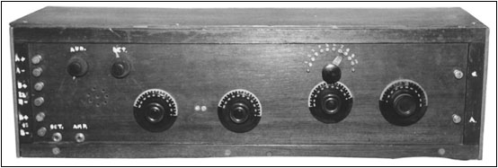
Figure 1. This example of an early home brew is a 2-tube regenerative set enclosed in a wooden cabinet about 21/2 feet wide. The panel, also made of wood, is hand-lettered in white paint.
De Forest-type Regenerative Set
The 3-tube home brew shown in Figure 3 is a fair copy of the early De Forest radios. The exposed coils are plug-in, diamond-wound inductors manufactured by Astoroid of Brooklyn, New York. Two knob-controlled worm gears set the degree of primary and tickler coupling to the central secondary coil. Two large variable capacitors control antenna and secondary tuning. A small variable capacitor shunts the main capacitor for vernier tuning. The switch on the upper-left panel is typical De Forest. It allows the antenna tuning capacitor to be connected in series, in parallel, or to be disconnected from the primary coil.
Individual rheostats control each tube filament. The tubes are marked "U.S. Army VT-5 Signal Corps." The VT-5 was designated "215A" by Western Electric, the manufacturer. This tube was often called the "peanut tube" because of its small size. It is a miniature version of a UV-199 and uses a filament voltage of 0.9-1.1. Figure 4 (see print version) provides an interior view. The audios are miniature types. The grid leak is adjustable. The battery terminals are raised on posts above the components. The wood cabinet is crude and seems crafted from house siding.
I bought the radio five or six years ago at a hamfest. As is usual with such finds, it required considerable cleaning before debugging could be performed. Of the three VT-5 tubes, only one was weak. Using the weak tube in the detector stage made the radio work quite well on the modern broadcast band. There was lots of interplay between the various controls, as well as considerable tuning effects from hand capacity, which is to be expected with exposed coils.
4-Tube Regenerative Receiver
Figures 5 and 6 (see print version) show the panel and parts layout respectively of an early 1920s 4-tube home brew using UV-199 tubes. In most regenerative receivers, regeneration was performed in the detector stage. This radio uses a regenerative radio-frequency amplifier preceding an untuned detector followed by two stages of audio amplification.
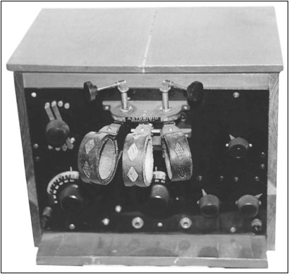
Figure 3. This ambitious home brew is a fair copy of early De Forest radios. The worm-geared coupling coils are impressive.
The RF stage is tuned by a large antenna variable condenser and a tapped inductor. Regeneration is controlled by a spherical Bakelite variometer.
The four large dials control the antenna capacitor, the plate variometer, and the filaments of the RF amplifier and detector. Two small knobs control the audio amplifier filaments. The pointer knob and metal dial-plate allow the radio to operate as a 2-, 3-, or 4-tube radio and also acts as the on-off switch. The wiring is white rubber-coated copper wire, which has survived intact over the decades.
I acquired this radio at a hamfest for a reasonable price. It required a good cleaning and some considerable debugging before becoming operational. The major problem was the 4-position switch which was designed to control the filament voltage to the tubes (turning the filaments off on unused stages) and simultaneously connect the single phone jack to the proper stage (detector, 1st audio or 2nd audio).
The only place I've seen this type of switching arrangement was in the early Paragon DA2 Detector/Amplifier. Most early designers preferred multiple phone jacks rather than complicated switching.
The cabinet of this set is typical "home-brew crude." The Bakelite panel has turned a soft gray with age and provides a nice contrast to the glossy black of the knobs and dials. As with many early home brews, the set operates only in the low end of the present broadcast band.
Early BC/Shortwave Home Brew
The panel of a restored home brew -- an early 1920s shortwave radio probably built by an Amateur -- is shown in Figure 7. I bought the radio as a junker via an A.R.C. ad. It was a true junker, and my first reaction was to strip it for parts. The baseboard was rotting, the panel was severely warped, the audio transformers and much of the wiring were missing, and there was no cabinet. However, the detector components were intact, including a 2-section coil with one coil mounted at a right angle to the other.
I traced the circuit which seemed unique -- a mixture of inductive (dual tickler coils) and capacitive (series capacitors) regeneration. Out of curiosity, I decided to test the detector; it worked so well (the single tube operated a loudspeaker on all local stations) that I decided to restore the entire radio. This entailed building a new baseboard, straightening out the panel (using heat and weights), a good cleaning (the tan coil forms and white wire of the coils cleaned up nicely with soap and water), adding audio transformers, and a complete rewiring. Figure 8 (see print version) shows the rear of the rebuilt radio. The panel was of standard size, and I had a spare cabinet on hand.
The tuning knobs and variable capacitors are by General Radio. Mechanical vernier tuning is via spur gears. The 2-position tap-switch on the right of the panel selects broadcast or shortwave operation. When in the shortwave position, the switch shorts out half of the tuning coil secondary to allow operation up to 2 megacycles. Regeneration is controlled by a series capacitor or by a variable resistor shunting one of the tickler coils. The meter is a milliammeter and uses a series resistor arranged to monitor the filament supply voltage.
With the bandswitch in the broadcast position, all local broadcast stations were received with good volume and fidelity. With the switch in the shortwave position, Amateur CW (Morse code) stations on the 160-meter Amateur band were received. By careful tuning and regeneration adjustment, I found that strong single-sideband (SSB) voice signals could be demodulated.
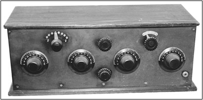
Figure 5. This 4-dialer is a 4-tube regenerative receiver with some different circuitry, as the text explains.
By the end of the 1920s, the advent of low-cost AC-powered radios probably killed the lust for home-brewed broadcast receivers, although the hams continued to brew their own communications equipment.
Henley's 222 Radio Circuit Designs, first published in 1924, is a comprehensive collection of early radio circuits and related information. It has been reprinted by Lindsay Publications and is highly recommended for anyone interested in early home brews.
Once again I must thank Alan Douglas for what little history I have included in this article. Gerald Tyne's Saga of the Vacuum Tube will provide as much historical and technical information as you could desire about early vacuum tube technology.
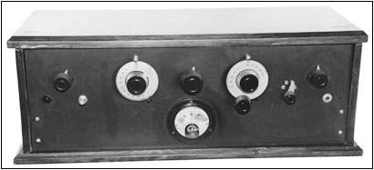
Figure 7. This 3-tube BC/SW home brew performed so well that the author restored it rather than strip it for parts.
References:
Douglas, Alan. Radio Manufacturers of the 1920's, Volume 1. Vestal, N.Y.: Vestal Press, Ltd., 1988.
Anderson, E. and Mills, C.C.; Henley's 222 Radio Circuit Designs. Bradley, Ill.: Lindsay Publications Inc., Reprint, 1989.
Tyne, Gerald F.J. Saga of the Vacuum Tube, Tempe, Ariz.: Antique Electronic Supply, 1987.
(William Corkutt, 26 Hillside Ave., Monsey, NY 10952)
Bill Corkutt has been seriously collecting old radios since he bought a junker 3-dialer at a hamfest in 1993. However, his interest in radio dates back to the early 1950s when he served as an army radio operator during the Korean War. He is a retired electrical engineer and operates Amateur Radio station WZ2I.
| [Free Sample] [Books, etc., For Sale] [Subscribe to A.R.C./Renew] [Classified Ads] [Auction Prices] [Event Calendar] [Links] [Home] [Issue Archives] [Book Reviews] [Subscription Information] [A.R.C. FAQ] URL = http://www.antiqueradio.com/Mar01_homebrew.html Copyright © 1996-2001 by John V. Terrey - For personal use only. Last revised: February 3, 2001. For Customer Assistance please contact ARC@antiqueradio.com or call (978) 371-0512 Pages designed/maintained by Wayward Fluffy Publications
Antique Radio Classified |