Of Old Radios And Related Items--Published Monthly
Gilding the Lily:
Circuit Evolution of the E.H. Scott Quaranta
and Custom Series Receivers from the
Full Range High Fidelity Receiverby Norman S. Braithwaite
WEB EDITION
In the 1930s, E.H. Scott Laboratories introduced enhanced models of its famous high-fidelity receivers. Norm Braithwaite describes the evolutionary process that produced the receivers of ever increasing complexity. Since 1987, Norman Braithwaite has contributed numerous articles to A.R.C. on the subject of E.H. Scott. (Editor)
During the early 1930s, the E.H. Scott Radio Laboratories became known for building the finest line of full featured, high performance receivers that could be built. The line started with their 12-tube "Allwave Superhetrodyne" receiver of 1931 and progressed through the 23-tube "Full Range High Fidelity" receiver of 1936. This set, is shown in Figure 1.
During this period, the E.H. Scott Radio Laboratories offered a single basic chassis layout and incorporated new developments and improvements as they became available. However Scott had held back from using single dial operation and continued to use 2-dial tuning to allow optimum oscillator and
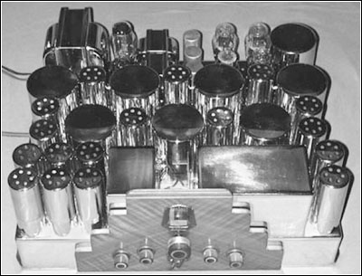
Figure 1. A front view of the 23-tube Scott Full Range High Fidelity receiver.
detector tuning resulting in superior sensitivity and selectivity. This was especially important for shortwave reception. Advancement to a single dial receiver, accommodated by improved tracking capability of the newer tuning gangs, justified the new model name "Allwave Deluxe". Other significant improvements were also incorporated.
New models names were assigned when the tube count changed or other improvements were made. Circuit variations associated with improvements are common among the individual models, especially the Allwave Fifteen.
By the mid-1930s, Scott's Full Range High Fidelity receiver boasted 13- to 550-meter reception using two stages of RF amplification, four stages of gain-compensated, continuously variable-selectivity IF amplification, separate bass and treble controls, and a 35-watt power amplifier driving a 12-inch bass speaker and two 5-inch tweeters.
Arguably, the Full Range High Fidelity receiver could be considered the finest and most practical all-wave high fidelity receiver of the 1930s. Further improvements to the Full Range High Fidelity receiver were limited to improving record reproduction, adding accessories, and keeping up with electronic component technology. The RF and IF circuits of the Full Range High Fidelity receiver were incorporated into the subsequent Philharmonic receivers with virtually no changes through 1941.
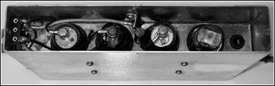
Figure 4. The Scott accessory volume range expander with the top removed.
Custom-Built Receivers
E.H. Scott recognized that not all potential customers would want or be able to afford a receiver incorporating all possible improvements; however, offering all possible improvements was necessary for marketing to the upper classes, Scott's largest market. Consequently, turntables, automatic record changers, deluxe amplifiers, tweeters and some other nonessential features were offered as options. By special order, custom receivers were built to meet the specific desiresof wealthy clients. These receivers often included phonographs, record lathes, special amplifiers, special cabinets and accessories.
Anyone who has spent much time researching the E.H. Scott Radio Laboratories or reviewing E.H. Scott literature is likely to be aware of the 40-tube "Quaranta" receivers custom built for a New York customer and for E.H. Scott himself, and of the 48-tube custom receivers built for John J. Mitchell and John Arnold.
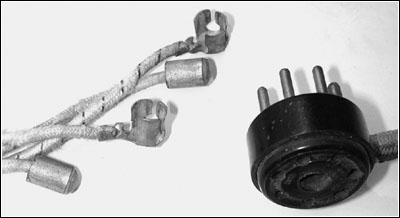
Figure 5. This adapter cable connects the volume range expander to the power supply and the tuner chassis.
The John J. Mitchell receiver is described in the May 1936 Scott News article and calls the Custom Receiver a Quaranta. (Note that Scott literature states that the name "Quaranta" was derived from the Spanish word for "forty." "Quaranta" is, in fact, the Italian word for "forty.") In that article, a photo of the receiver chassis clearly shows the presence of a record amplifier hence the receiver was definitely a 48-Tube Custom Receiver as identified in the April 1936 Scott News article. The Mitchell receiver was also rumored to have had 57-tubes. This may be true if the receiver was modified to a 50-tube version (second 50-tube version described following) and an accessory amplifier (similar to the record amplifier) was added to drive additional speakers. There is another rumor that Mr. Mitchell owned both a Quaranta and a 48-Tube Custom Receiver. This is unlikely due to the obvious use of the name "Quaranta" used in reference to a 48-Tube Custom Receiver in the May 1936 Scott News and because no second receiver was disclosed when Russ Mappin interviewed John Mitchell many years ago.
Other Variants
Less well known are the 27-tube version of the Full Range High Fidelity receiver, now sometimes referred to as "Mini Quaranta," and the two 50-tube versions of the Custom Receiver series.
Available Data
At the present time, no schematics have been located for the 27-tube version of the Full Range High Fidelity receiver or the Quaranta. Schematics for the tuner and mid-amplifier of a 50-tube variant of the Quaranta came to the attention of collectors in 1988 after collectors had become acquainted with Murray Clay, Chief Engineer of the E.H. Scott Radio Laboratories prior to Marvin Hobbs.
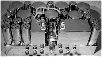
Figure 8. The 19-tube tuner chassis used in the Quaranta series of Scott receivers.
From these schematics, from one existing tuner and mid-amplifier chassis (found by Earl England in the late 1970s, serial no. X494) and from the few other original chassis associated with the Quaranta and Custom series receivers, the general circuits of most of the Custom series and the 27-tube version of the Full Range High Fidelity receiver have been identified. Although the progression of these circuits is described in order of complexity, their probable order of appearance on the market is shown in Table I.
Scott Radio Laboratories introduced the 30-tube Philharmonic model in April 1937 ending the long run of chassis based on the layout developed for the Allwave Superhetrodyne receiver.
Full Range High Fidelity Receiver:
The Full Range High Fidelity receiver had been introduced as the "Allwave Imperial" in March 1935. It was renamed within a couple of months to better attract the attention of customers. Customers who had purchased the receiver before it was renamed were sent "corrected" instruction manuals with the new receiver name on the cover (the only correction!). This Full Range High Fidelity receiver, which was probably the best designed receiver of the 1930s, evolved from E.H. Scott receivers dating back to 1931.
The chassis layout for the tuner chassis of this receiver is shown in Figure 2 (see print version).
Full Range High Fidelity Receiver with Accessory Volume Range Expander
An accessory volume range expander (VRX), shown in Figures 3 (see print version) and 4, was introduced for the Full Range High Fidelity receiver in March 1936. The VRX unit employs the following tube types: 76 rectifier, 6C6 amplifier and two 6A7 expanders. Power for the 4-tube expander unit was tapped from the Full Range High Fidelity power supply using the special adapter cable shown in Figure 5. The audio signal was taken from and returned to the tuner chassis at the grids of the second audio frequency amplifiers. Installation of an accessory volume range expander produced a total tube count of 27 tubes, but their functions differed from those of the soon to be introduced Full Range High Fidelity receiver with integral volume range expander.
Full Range High Fidelity Receiver with Integral Volume Range Expander
The time when the Full Range High Fidelity Receiver with an integral volume range expander was introduced is not well known, but it is certain to be after the introduction of the Quaranta and likely a few months after introduction of the accessory volume range expander. Its chassis layout is shown in Figure 6 (see print version). This receiver was offered concurrent with the more familiar 23-tube version of the Full Range High Fidelity receiver without a volume range expander.
The expander circuit was accommodated by replacing tubes that provided the BFO and meter amplifier functions and moving the push-pull second audio amplifier stage to the power amplifier chassis. Two "eye" tubes were added to the tuner to indicate signal strength and degree of volume expansion.
This receiver provided the same essential functions as the previously introduced Quaranta and was offered as a much lower cost alternative to the Quaranta. Unfortunately, the E.H. Scott Radio Laboratories did not publicize this receiver in their brochures, price lists or news organs; therefore, less is known about this receiver than most others.
The Quaranta
The Quaranta, shown in Figures 7 (see print version) and 8, was introduced in December of 1935 as the "most perfect sound reproducing instrument that could be designed regardless of cost". The receiver could be purchased for $2,500 in 1936. A search of Scott literature yields references to only two of these receivers. One of these is the receiver constructed to fulfil the order from an unnamed New York customer and the other for E.H. Scott himself. No examples of a 40-tube Quaranta are known to exist today.
In addition to being housed in two separate consoles, the Quaranta differed from the Full Range High Fidelity Receiver (its direct predecessor) by the addition of an on-board volume range expander, a "mid-amplifier," a two channel power amplifier, and a high quality theater speaker system. In addition to providing voltage amplification, the mid-amplifier divided the audio signal into a bass frequency band below 125 Hz and a mid- and high-frequency band above 125 Hz.
The power amplifier was essentially two Full Range High Fidelity Receiver power amplifiers constructed side by side on a single chassis. The power amplifier was described by the E.H. Scott Radio Laboratories as providing 50-watts of "undistorted" power per audio channel. The bass amplifier was used to drive an 18-inch Jensen theater speaker. The mid- and high-frequency amplifier was used to drive a single 12-inch Magnavoxmidrange speaker and a pair of Jensen "Q-Series" horn type theater tweeters. The function of the 40th tube remains unknown today.
Scott 48-Tube Custom Receiver
Shortly after introducing the Quaranta, the E.H. Scott Radio Laboratories produced a similar receiver, the 48-tube Custom Receiver shown in Figures 9 (see print version), 10 and 11. This model added the capability to cut records. A 7-tube recording amplifier, shown in Figure 12, was created from the power amplifier of a Full Range High Fidelity receiver by modification to include an extra stage of voltage amplification.
The Full Range High Fidelity receiver power amplifier relied on a speaker field coil for filtering. Rather than create a new chassis for a choke and output transformer, the E.H. Scott Radio Laboratories mounted a standard 12-inch Full Range High Fidelity receiver speaker against the inside wall of the receiver cabinet and plugged it into the record amplifier to provide the needed functions. The voice coil leads of the speaker were disconnected and the signal from the output transformer routed to the cutting head on the record lathe. Along with an additional midrange speaker in the speaker console, this produced a total speaker count of six, but only five were used for sound reproduction. An additional 2-tube microphone preamplifier chassis (bringing the total tube count to 48,) shown in Figure 13, and dual ribbon Amperite microphone were also included with the receiver.
The record lathe was a 12-inch Presto model mounted adjacent to a Garrard automatic record changer on a shelf below the tuner. The recording amplifier, the microphone preamplifier and the relay power supply (shown in Figure 13) were installed below the turntable shelf. The relay power supply provided 24-volts DC to operate an AC power relay in the main power amplifier that had been moved to the base of the speaker console. Use of AC for this function would have produced objectionable hum.
A selenium rectifier was used for rectification of the relay supply current rather than another tube. (The relay supply and power relay was not needed in the 40-tube Quaranta because the power amplifier was housed in the receiver console and AC lines were easily separated from the speaker signal.)
Scott literature identifies two of these receivers that were built, one for John J. Mitchell of Santa Barbara, California, and one for John Arnold in Hollywood. These receivers were probably sold for around $3,000. Three power amplifiers from 48-Tube Custom Receivers or larger variants have been found to date. The only completely original "Quaranta" type Custom Receiver presently known to exist is being restored as a 48-tube version.
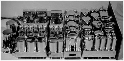
Figure 10. Below, a side view of the Scott 48-tube Custom Receiver. Note that the placement of the record cutting amplifier and the power supply/power amplifier are interchanged from the chassis layout.
50-Tube Custom Receiver,
First VariantUnbeknownst to the public, the radio industry, and radio collectors alike until after the mid-1980s, the E.H. Scott Radio Laboratories manufactured more elaborate receivers. During the early 1980s a complete set of three console cabinets was found with a 16-inch Presto recording lathe, Capehart automatic record changer, and all of the unique supporting chassis associated with the models containing 48 or more tubes. The tuner and mid-amplifier chassis for this receiver had been removed many years earlier and have never been found. Photos of this exceptional receiver are included in the second edition of E.H. Scott, Dean of DX by Marvin Hobbs.
Although we may never know for certain if this particular receiver was a 50-tube variant, one piece of evidence lends a strong argument that it was. The receiver had been owned by Mr. Beardsley, co-owner of the Beardsley and Piper Company in Chicago, which manufactured equipment used by foundries throughout the world. In 1939, the Beardsley and Piper Company hired Murray Clay from the E.H. Scott Radio Laboratories. Mr. Clay was an accomplished inventor and was responsible for technical development of the Full Range High Fidelity Receiver, for the Quaranta, and for several patents during his tenure at the E.H. Scott Radio Laboratories. Mr. Clay was personally acquainted with the Beardsley family and, while still working with the E.H. Scott Radio Laboratories, designed an automatic control system for sand packing molds of large castings.
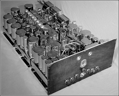
Figure 11. A 3/4 view of the Scott 48-tube Custom Receiver.
It is believed that this work "on the side" was ultimately the reason for Murray's discharge from the E.H. Scott Radio Laboratories. Murray and Mr. Beardsley remained well acquainted until Mr. Beardsley's death in 1951. After Murray had come to the attention of radio collectors, it was found that he had kept blueprints of the tuner and mid-amplifier schematics for a 50-tube variant of the Quaranta. The blueprints are indisputable proof of the existence of 50-tube variants and were most likely retained to assist in maintaining the receiver purchased by Mr. Beardsley.
The first 50-tube variant differed from the 48-Tube Custom Receiver in the addition of a record scratch suppressor, an early version of a dynamic noise suppressor, plus replacement of some tubes with newer octal types. The scratch suppressor addition was placed on the tuner and was accommodated by moving the expander tubes to the mid-amplifier chassis. Two filter capacitors on one end of the mid-amplifier chassis were removed to accommodate the expander tubes. Figure 14 (see print version) shows the modified chassis layouts of the mid-amplifier and tuner.
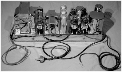
Figure 12. The recording amplifier used in the 48-tube custom receiver.
Unfortunately this new addition required physically connecting the tuner chassis and mid-amplifier chassis and routing eight wires through new holes between the chassis (resulting in a single chassis of size and weight rivaling RCA's first consumer color television chassis).
According to Mr. Beardsley's widow, the receiver cost $3,500. Of this she was sure! (Personal communication, 1985.) The elaborate 3-console, 50-tube variant was not advertised or disclosed anywhere in literature of the E.H. Scott Radio Laboratories. This may have been due to E.H. Scott Radio Laboratories having already sold several lesser receivers under the pretence of being the most elaborate they would ever build.
50-Tube Custom Receiver, Second Variant
Although not originally recognized as such, the chassis set found by Earl England during the 1970s was part of a 48-Tube Custom Receiver later modified to a 50-tube variant. See Figure 15 (see print version). The modifications in the tuner and mid-amplifier chassis were not well understood until the blueprints saved by Murray Clay came to the attention of collectors and were compared to the chassis.
The modifications were recognized as having been made during the late 1930s and substantially recognized as an added record scratch suppressor, but it was not known if the modifications had been conducted by the E.H. Scott Radio Laboratories or by others. Comparison of the chassis to the schematic confirmed that the modifications included adding a record scratch suppressor in the same manner as identified on the schematic.
Figure 13. The microphone preamplifier (left) and the relay power supply (right) used in the 48-tube custom receiver.
Other modifications consisted of replacing some tubes with more modern octal equivalents. Given the correlation between the Scott schematic and the receiver circuit combined with the materials and construction practices employed, the modifications could only have been conducted by the E.H. Scott Radio Laboratories.
The author wishes to recognize John Meredith, Kent King and Craig Korpac for assistance with some of the historic details presented in this article.
References:
Scott News, E.H. Scott Radio Laboratories: V8, N1, March 1935; V8, N12, December 1935; V10, N2, March 1936; V9, N3, April 1936; V9, N4, May 1936; V2, N10, April 1937.
Antique Radio Topics and Classic Radio Collectors Newsletter, Puett Electronics, V10, N7, undated, 1980.
(Norman S. Braithwaite, P.O. Box 992443, Redding, CA 96099; normb@awwwsome.com)
In 1975, Norman Braithwaite, a civil engineer, began collecting antique radios, especially those manufactured by E.H. Scott and its competitors. His collection includes representative sets from 1917 to 1960, the prize being a rare Scott 48-tube custom receiver.
�
| [Free Sample] [Books, etc., For Sale] [Subscribe to A.R.C./Renew] [Classified Ads] [Auction Prices] [Event Calendar] [Links] [Home] [Issue Archives] [Book Reviews] [Subscription Information] [A.R.C. FAQ] URL = http://www.antiqueradio.com/May04_Braithwaite_Quaranta.html Copyright © 1996-2004 by John V. Terrey - For personal use only. Last revised: April 30, 2004. For Customer Assistance please contact ARC@antiqueradio.com or call (866) 371-0512 Pages designed/maintained by Wayward Fluffy Publications
Antique Radio Classified |