
Of Old Radios And Related Items--Published Monthly
Early Home Brews with Grid-Leak Detectors
BY WILLIAM CORKUTT
Web Edition
Early detectors came in various forms, but all had a common shortcoming -- poor sensitivity. The DeForest Audion and later triodes, combined with Armstrong's regenerative circuit, produced receivers with greatly improved sensitivity. The following article describes some examples of radios that employ grid-leak detectors. (Editor)
As early as 1916, David Sarnoff, future president of RCA, envisioned a music-box in every home whereby music, news, entertainment, and culture would be received by wireless. The feasibility of radio broadcasting was proved in 1920 when KDKA of Pittsburgh began broadcasting scheduled programs. The broadcast boom finally came in 1922 when everyone wanted to get into radio. Early commercial radios were expensive, so as components became more available, radio amateurs and experimenters built their own.
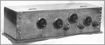
Figure 1. A panel view of an early capacitive feedback radio.
A Tuned-Grid, Tuned-Plate Radio
Figure 1 shows the panel of an early 1920s home-brew regenerative radio that employs a grid-leak triode detector. It is obviously a home brew, for there are no panel markings, no stops on the tap switches, nor any identification as to the maker. The panel measures 7" x 26" and is of varnished wood rather than Bakelite or hard rubber. The panel includes the characteristic peepholes (a hexagonal pattern, in this case) for viewing the filament color. Cherry-red was usually specified as the proper filament rheostat setting.
The rear view of the receiver is shown in Figure 2. A large variable capacitor and two tap switches on the primary of the antenna coil tune the antenna circuit. The secondary rotates within the primary to provide variable coupling. A large wooden variometer in series with the secondary tunes the grid circuit of the tube. A second variometer in the plate circuit controls regeneration. The grid capacitor and grid-leak resistor are a single unit with the variable grid-leak resistor controlled by a small knob.
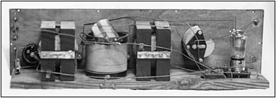
Figure 2. A component view of a capacitive feedback radio.
I obtained the radio from an A.R.C. contact. It was very dirty but otherwise intact. The wire of one variometer rotor coil had unwound and required a complete disassembly of the unit. This process provided the opportunity to study the construction of wood variometers.
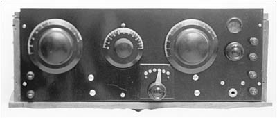
Figure 3. The panel of an inductive feedback radio.
These wood variometers were manufactured by the New York Coil Company and are solidly built of hardwood and heavy wire with strong spring contacts on the rotor shafts to provide good conductivity. Each variometer has a red warning label pasted on the top reading, "Not Sold for Use on Patented Circuits." The label is ironic in that this was exactly what the original builder had done, since the circuit is obviously Armstrong's.
The radio tunes the low end of the present broadcast band up to about 1200 Kilocycles. The major drawback of the tuned-grid, tuned-plate regenerative receiver was that the plate circuit had to be retuned with each new setting of the antenna controls and grid variometer. This process made for difficult station-finding.
An Early Inductive Feedback Radio
Figure 3 shows the panel of an early inductive feedback grid-leak detector. The radio is robust both in size and components. The panel measures 7" x 18" and the large knobs are 4" in diameter. It may have been a kit, for the peephole is screened and it's doubtful that a home-brewer could craft the screen and associated metal bezel. The tap switch for varying secondary inductance is mounted on a small Bakelite subpanel of its own.
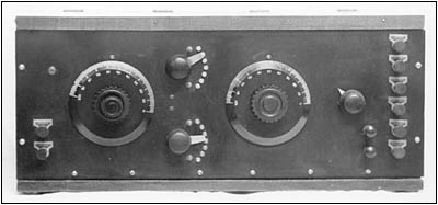
Figure 5. A panel view of a later grid-leak detector receiver.
Figure 4 (see print version) is the rear view. What attracted me to the radio was the robust size of its components. The antenna tuning variable-capacitor on the right of the picture measures 41/2"in length and 4" in diameter. Its 43 plates result in 780 picofarads of capacitance. The coil measures 6" high x 4" in diameter. The top winding is the primary in series with the antenna capacitor.
The second variable capacitor has the same frame as the antenna capacitor. It has 23 plates and shunts the large secondary winding in the usual fashion. A rotating wooden tickler coil controls regeneration which was to be the standard technique for some years. The clip-in type grid resistor is fixed. There is no baseboard, and all components are attached to the back of the panel. There is little soldering, as most connections are of the screw type.
I obtained the radio from an A.R.C. ad. It was remarkably clean but only partially wired. However, a bundle of preformed bus-bar came with the radio and enabled me to finish the job as the original builder intended. There are no markings on the panel nor on any of the components. As is usual with very early radios, it operates only in the low end of the present AM broadcast band.
A Later Grid-leak Detector
Figures 5 and 6 (see print version) show the front panel and rear view respectively of what was to be the typical 1-tube radio for some years. It is a big radio with a 19" x 7" panel and 4" knobs for tuning and regeneration control. It is a bit more elegant than most home brews in that metal nameplates identify the function of each binding post.
The two tap switches have stops which were often ignored on home brews. A second set of binding posts, in parallel with the phone binding posts, allows two sets of earphones to be connected simultaneously. A small concentrically mounted knob on the tuning dial controls one plate of the variable capacitor for vernier tuning.
The rear view shows further refinements. The tuning/tickler coil is a commercial unit. To inhibit the effects of hand capacity tuning, tinfoil has been pasted on the rear of the panel in front of the tuning capacitor and the tuning coil. Some of the wiring consists of copper straps which seem pure overkill.
The grid leak is of the variable type. Regeneration is controlled by a rotating tickler. The peephole has been dispensed with since the set was probably meant for the newer UV201-A type tube, a tube requiring only 1/4 ampere of filament current. The radio tunes the lower end of the broadcast band.
Early 1920s Amateur Grid-leak Detector
By 1921, the commercial and amateur services were making the transition from spark telegraphy to vacuum-tube technology. Vacuum tube transmitters produced a pure continuous wave (CW), which was keyed on and off for Morse code transmission. To receive CW, the receiver detector was made to oscillate continuously. The oscillating detector beat against the keyed signal to produce an audio frequency.
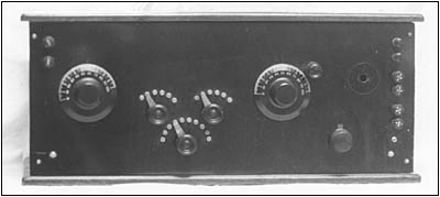
Figure 7. A panel view of a Reinartz Amateur receiver.
John Reinartz, a well-known Amateur, designed a detector circuit that combined capacitive and inductive feedback by using a specially wound spiderweb coil that had tapped primary, secondary and tickler windings.
Figure 7 shows the panel of a typical Reinartz grid-leak detector. It is a big radio, with the panel measuring 20" x 8". The cluster of three tap-switches are typical of Reinartz receivers, and they select the individual windings of the spiderweb coil. The two large knobs control tuning and regeneration on the selected portion. Once the regeneration controls are set, all tuning is via the tuning dial. Since tuning is very sharp, a small knob mounted above the tuning dial provides vernier tuning.
Figure 8 shows the rear view. The spiderweb coil is mounted on a bracket for stability. The numerous taps are on the unseen side of the coil. The filament rheostat is of the compression type, the fine threads of the compression-screw providing fine filament control. There is a peep-hole; however, the tube is not in line with it. I surmise that the builder may have upgraded his radio to use the more modern Type 201-A tube, and, consequently, remounted the tube near the tuning components for shorter leads.
The radio tunes the entire modern broadcast band up to about 1600 kilocycles. This was adequate in 1921 since Amateurs were restricted to 200 meters (1500 Kilocycles) operation. Although primarily meant for Amateur use, the Reinartz circuit was popular with the public and many were homebrewed for broadcast reception during the radio boom of 1922-1923.
Epilogue
What had these early grid-leak detector radios in common? First, one must admire their classic simplicity -- there were no extraneous parts or frills -- and they performed the task they were designed for well. They were handcrafted and mounted in sturdy cabinets as if meant to last forever.
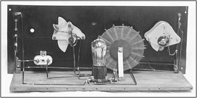
Figure 8. A component view of a Reinartz Amateur receiver.
Recommended Readings
For those interested in the history and technology of early vacuum-tube radios, I would recommend the following:
The Legacy of Edwin Howard Armstrong, published by the Radio Club of America, is a collection of articles by and about Armstrong and his inventions. The book contains his original 1915 paper, "Some Recent Developments in the Audion Receiver" and describes in detail the operation of the triode, the discovery of feedback, and early regenerative circuits.
For a detailed history of the radio patent wars which embroiled Armstrong, DeForest, and Sarnoff, there is Tom Lewis's Empire of the Air. In addition to legal and technical aspects, the book contains a wealth of information on the lives and personalities of the men involved.
The Wireless Experimenter's Manual of 1920 by Elmer Bucher is a complete presentation of the radio art in 1919 just before the era of broadcasting. It describes how experimenters (usually amateurs) could build their own spark transmitters, crystal detectors, and early vacuum-tube radios. Besides the practical aspects of home-brewing, this manual includes as much radio theory as was known at the time. An interesting read in itself, it has been reprinted by Lindsay Publications Inc.
Henleys' 222 Radio Circuit Designs of 1924 contains much information on early radio and includes the circuits of the grid-leak detectors presented in this article. It has been reprinted by Lindsay Publications Inc.
The January 1999 issue of Antique Radio Classified contains an article on "Reinartz Home Brews" which includes the Reinartz circuit and pictures of 2- and 3-tube Reinartz receivers.
References:
Anderson, John, Arthur Mills, and Elmer Lewis. Henley's 222 Radio Circuit Designs New York: Henley Publishing Co. 1924. Reprinted by Lindsay Publications Inc., 1989.
Bucher, Elmer E. Wireless Experimenters Manual. New York: Wireless Press, Inc., 1920. Reprinted by Lindsay Publication Inc. 1992. Bradley, Illinois.
Corkutt, William. "Reinartz Home Brews," Carlisle, Mass.: Antique Radio Classified, January 1999.
Lewis, Thomas. Empire of the Air. New York: Harper Collins, 1991.
The Radio Club of America. "The Legacies of Edwin Howard Armstrong," 1990
(William Corkutt, 26 Hillside Avenue, Monsey, N.Y. 10952)
Bill Corkutt has been collecting old radios since he bought a junker 3-dialer at a hamfest in 1993. His interest in radio dates back to the early 1950s when he served as an Army radio operator during the Korean War. He primarily collects and repairs early battery home brews. He is a retired electrical engineer and operates Amateur Radio station WZ2I.
What Is A Grid Leak?
Compiled from S. Gernsback's Radio Encyclopedia 1927
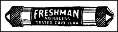
In simple terms, a "grid leak" is the resistor placed in the grid circuit. The figure at right shows typical fixed and variable grid leak resistors.
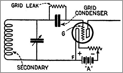
Why is a grid leak used? In order to function as a detector or amplifier, the grid of vacuum tubes must be a few volts negative, the "grid bias." The combination of a grid leak resistor in parallel with a condenser, as shown in the schematic below, allows the small current flowing to the grid to produce this negative voltage naturally.
Following are excerpts from from S. Gernsback's Radio Encyclopedia 1927 to further explain, "What is a grid leak?"
Sidebar, figure A.
GRID LEAK -- A high resistance placed in the grid circuit of a vacuum tube to permit the electrons forming the grid current to leak off after each charge thus preventing their accumulating on the grid in such numbers as to stop the flow from the filament.
The grid leak may have a value ranging from about 250,000 ohms to several million ohms. The value of a grid leak is generally stated in megohms -- one megohm being one million ohms. Thus a grid leak of 250,000 ohms resistance would be referred to as a 1/4-megohm leak and, similarly one having a resistance of two million ohms would be referred to as a two megohm grid leak.
Sidebar, figure B.
Such resistances are furnished in many forms, the most common being a strip of paper impregnated with graphite or some similar high resistance preparation, placed in a glass tube and sealed to prevent moisture from affecting the value. The illustration shows a tubular type of a fixed grid leak.
Variable grid leaks, the resistance of which can be changed at will, are also furnished in an infinite variety of types, one of which is shown in the figure.
For experimental work a fairly satisfactory grid leak can be made by the simple expedient of drawing a line on a piece of cardboard with a soft pencil. --the graphite mark acting as the resistance. At each end of the cardboard is placed a binding post in contact with the graphite, each binding post being connected to opposite sides of the grid condensers.
GRID CONDENSER -- A small fixed condenser, generally from .00025 to .0005 microfarad capacity, inserted in the circuit of a detector tube between the tuning coil and the grid member of the tube. The illustration shows the manner of connecting the grid condenser in a conventional detector circuit. This condenser insulates the grid from the filament by breaking the path F to G and permits the tube to act as a rectifier or detector. A resistance (called grid leak) is usually placed across this condenser to allow the accumulated charges on the grid to leak off [and place a negative voltage on the grid.]
GRID BIAS -- A potential of a few volts, generally from four to six, applied to the grid of a vacuum tube. The grid bias is usually negative and determines the point of the characteristic curve at which the tube will operate.
Sidebar, figure C.
| [Free Sample] [Books, etc., For Sale] [Subscribe to A.R.C./Renew] [Classified Ads] [Auction Prices] [Event Calendar] [Links] [Home] [Issue Archives] [Book Reviews] [Subscription Information] [A.R.C. FAQ] URL = http://www.antiqueradio.com/Oct02_Corkutt_gridleak.html Copyright © 1996-2002 by John V. Terrey - For personal use only. Last revised: September 18, 2002. For Customer Assistance please contact ARC@antiqueradio.com or call (866) 371-0512 Pages designed/maintained by Wayward Fluffy Publications
Antique Radio Classified |