
Of Old Radios And Related Items--Published Monthly
Golden-Leutz Universal Transoceanic
"Phantom" Type 9BY DANIEL SCHOO
Web Edition (Excerpted from the Print Edition)
Sometimes Lady Luck smiles, as she did for Daniel Schoo. In this article, he tells about how he acquired and restored a Golden-Leutz radio. His patience and restoration skills are to be admired. Read on. (Editor)
I never set out to own a Leutz radio. My interests are more centered on 1930s through 1950s wood table radios, but as often happens, a radio falls into your lap quite by accident.
One evening in September of 2006 my wife Donna and I were visiting some friends out of town. My friend Ed had a friend who was moving to Wisconsin and wanted to lighten the load. Ed asked me if I was interested in an old radio that his friend Doug wanted to get rid of.
Now, when somebody asks me this, I usually get the image of a 1980s era boombox in black plastic, spattered with paint, a coat hanger antenna and the cassette door broken off. I always ask politely for a little more information because I have this secret fantasy that someday somebody is going to be cleaning a Zenith Stratosphere (of the first 100 serial numbers, of course) out of the basement, and it would be just my luck to turn it down without asking.
The answer came the following week when Ed asked if I'd ever heard of a Golden-Leutz. The name Leutz sounded familiar and I was interested. I found a couple of articles about Leutz radios online in the Antique Radio Classified archives. Hey this looked better and better! I called Doug and set up an appointment to go get it. So one afternoon I took a trip to Naperville, Illinois, only a couple of miles from where I work, to pick it up.
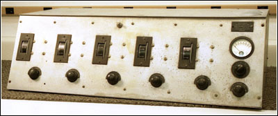
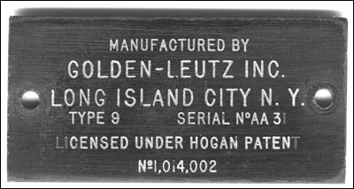
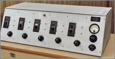
At first sight it looked different from other old battery type sets I have seen. Figure 1 shows the set as found. The nameplate, shown in Figure 2, identified it as manufactured by Golden-Leutz Inc., Long Island City, N.Y. The only other identifying information was "Type 9" followed by a serial number below the manufacturer's name. At the bottom of the nameplate licensing was credited to a Hogan Patent #1,014,002.
Figure 1. The Golden-Leutz Universal Transoceanic in its as-found condition.
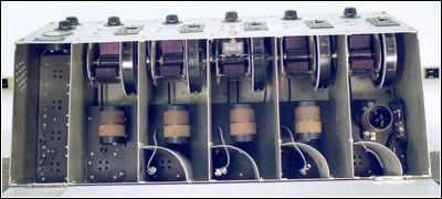
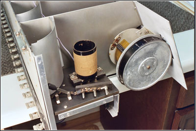
Figure 2. The radio's nameplate shows it to be a Type 9. As explained in the text, it is also a "Phantom" version of the Universal Transoceanic.Giving it a quick once-over, I observed that the radio was a 4-stage TRF set. There were five tuning controls, first through fourth RF and detector. Figure 3 shows an inside view of the set. Most striking was the cabinet made entirely of thin gauge sheet aluminum, sandblasted with a very dull matte finish. It was unlike the fine finished woods and glossy black panels of most battery sets. It was in reasonably good condition with some water staining and corrosion on the lid and front panel and the usual dirty film all over...
Figure 3. This view of the RF section shows the missing tubes and the grid connections.Two Universal Transoceanic Models
I learned that the radio I had was one of a series called the "Universal Transoceanic." "Transoceanic" was all one word, unlike the later and more familiar Zenith portable models that were hyphenated as "Trans-Oceanic." The first advertisement to announce the redesigned Universal Transoceanic using "222 Screened Grid Tubes" was in the July 1928 issue, only months after the Type UX-222 tube was introduced by RCA.
I discovered that Leutz made two models of the Universal Transoceanic. The first was called the "Silver Ghost" and it was built in separate units as described in the Bintliff article. Each unit was one stage of Radio Frequency (RF), Detector or Audio Frequency (AF) amplifier in its own aluminum box. The units were set up side by side and connected together with jumper wires from stage to stage attached to binding posts on the front panels. Each unit was powered independently by its own set of internal batteries. This had to be a royal pain for maintenance.
The Silver Ghost was a custom-built set, as described in the May and June 1928 issues of Radio News. According to the advertisement, each Silver Ghost was "custom built to the particular requirements of each customer." This explains the sample-to-sample differences in the Silver Ghost and the reason for the modularity. The photograph in the advertisement shows a radio very much like the one described in Ray Bintliff's A.R.C. article. It was a big behemoth of a set.
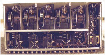
The second type was called the "Phantom." The Phantom was built in one long cabinet with each stage separated by an aluminum shield inside. It was somewhat smaller with dimensions of 81/4 inches high by 271/4 inches wide by 131/4 inches deep at the base. The slant-front cabinet sloped to a dimension of 93/4 inches deep at the top. It weighed about 31 pounds. The power was bussed internally and shared by all of the stages. A bottom view of the chassis is shown in Figure 7, while Figure 8 (see print version) provides a close-up of the tuning capacitors, drum dials, and one of the compensating capacitors.
The previous versions of the Phantom used Type UX-201A tubes in the RF stages. Several new improvements were announced such as the use of the new Type UX-222 tube and a redesigned audio section with push-pull output for increased power. Some "BC" (B+ plate and C bias voltage) power supply improvements were listed implying that the set was operated from AC house current. A 6-volt storage battery could be used for the filaments. The advertisement noted that the addition of a Leutz "A" current supply of 6 volts at 3 amperes allowed the set to operate completely from AC power.
An interesting side note was added in small print at the bottom of the July 1928 ad. It stated that present owners of Transoceanics could send their sets to the factory to have the improvements added at a nominal cost.
Each Phantom was sold only by special order with delivery in three to six weeks after confirmation of the order. The price quoted in an October 1928 advertisement was $250 "completely constructed and laboratory tested (no accessories)." That is the equivalent of over $2,800 in 2006 dollars. It is unknown whether the power supply and the tubes were considered accessories. Certainly the speaker and antenna were. This was definitely a high-end set. "Constructional blueprints" could be bought for $2.
Figure 7. This bottom view of the chassis provides another view of the radio layout and components.The October 1928 ad also listed most of the tube complement of four UX-222 RF amps, a UX-200A detector and a push-pull output stage that could use either a pair of UX-210s or UX-250s. The remaining two audio preamp tubes were unidentified, but they were most likely UX-201As, as had been used in previous versions. It was stated in a December 1928 ad that, in the two years prior, fewer than one thousand of the Phantoms had been built.
Radio Construction
The thumbwheel tuning dials on the Phantom are marked with an arbitrary zero to 100 scale progressing upward as you rotate the dials downward. An arbitrary scale is necessary since the actual reception frequencies depend on which set of RF coils are installed in the set. The wavelength increases (frequency decreases) as you rotate the dial from zero to 100.
Since everything was in one cabinet, all five of the tuning knobs could be ganged together simply by tightening a screw on a shaft coupler between each stage if desired. While this was possible, it was probably not practical for the usual reason that perfect tracking of the five tuned circuits was unlikely. Some compensation for uneven tracking was provided with fine tuning controls called resonators on the 1st and 4th RF stages. As found, my set had the 1st RF tuning control independent and the other four stages were locked together. Figure 9 shows the 1st RF stage. Other controls included RF filament, detector (filament) and a volume control.
Strangely enough, the volume control is backwards from the usual sense. You rotate it counterclockwise to turn the volume up. Most pre-automatic-gain-control DC filament sets controlled the volume by adjusting the gain of the tubes with the amount of filament current. This set also has that capability. The volume control was not connected as a potentiometer as in modern sets. It was simply a variable resistance shunting the audio signal to ground at the input of the second audio tube. In addition to the other controls there is a panel mounted voltmeter and an associated nine position circuit selector switch provided to measure the various operating voltages...
There were at least two versions of the Phantom. I am not familiar with all of them nor could I find anything in web searches or in other archives. The schematic for an earlier version using Type UX-201A tubes is commonly available in publications such as the Gernsback Official Radio Service Manual of 1930 and the Rider Manual, Volume I. There were no schematics that I could find for the screen grid version of the Phantom.
The screen grid version shares a lot in common with the earlier triode version. The cabinet design is nearly identical. The main visible difference is the addition of two domes in the lid on the far right side. These were added to provide additional room for a pair of high power push-pull audio output tubes.
Cosmetic Restoration
I began the restoration on two fronts, cosmetic and electronic. Cosmetically, the cabinet was water stained and freckled with corrosion spots. Unlike the lacquer finishes on old wood cabinet sets, the original sand-blasted factory finish on this one was easily duplicated.
One thing I noticed about the finish was that the sand blasting was done very poorly. The texture was uneven and some areas were seriously over blasted. This shows up as a coarse mottled appearance where the blaster was held too long or excess pressure was used and the surface of the aluminum became slightly eroded. Swirling and changes in texture showed up where uneven blasting was done.
I removed the top, bottom, sides and front panel. The back was riveted to the frame and not easily removable. Luckily, the back panel was not corroded. A good cleaning with a spray cleaner perked it up, and it looked like new. Disassembly of the panels was rather easy by removing a number of screws holding the sections together. The front panel escutcheons covering the tuning wheels were attached with screws. For the other controls, the control mounting nuts held the escutcheons on.
Figure 9. A closeup of the 1st RF stage showing the tuning capacitor, drum dial, plug-in coil and a knife switch which selects the antenna length.I removed all of the switches, controls and meter from the front panels, and I placed each of the panels in an enclosed beadblaster. Inside the beadblaster is a hand-held gun operated by compressed air that propels small glass shot, much like a spray paint gun sprays paint. The beads blasted away most of the dirt, corrosion and scratches leaving a factory original matte finish. Some pitting was still visible as a mottling of the surface, but it was far less noticeable than before. A final wet rubdown with a medium ScotchBrite pad took off the roughness that raw bead blasting leaves on a surface. Figure 11 (see print version) shows both the original and restored front panels...
The tuning wheel escutcheons, shown in Figure 12 (see print version), were obviously handmade too. The openings were not true and square. The bevels around the outside were uneven as though they had been cut by hand on a belt sander. Also where the mounting holes were drilled you could still see the scribe lines someone had scratched on the back indicating the drill locations.
The holes for the mounting screws in the chassis parts were drilled and not deburred. The holes were tapped and 6-32 machine screws were driven into the sixteenth-inch aluminum with no reinforcing inserts. This seems to have been sufficient in most locations, except the bottom panel where some of the holes had stripped-out threads.
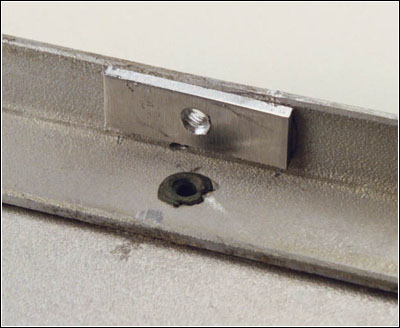
To reinforce the stripped-out threads, I cut small aluminum plates 1/4" wide by 3/4" long. I drilled a hole in the center of each and hot-melt glued the plates to the inside of the chassis, aligning the holes in the centers of plates with the screw holes in the chassis. Once the plates were in place, I tapped the holes through the existing threads in the chassis. This fix provided a secure thread for the bottom screws. Figure 13 shows an example of this repair technique...
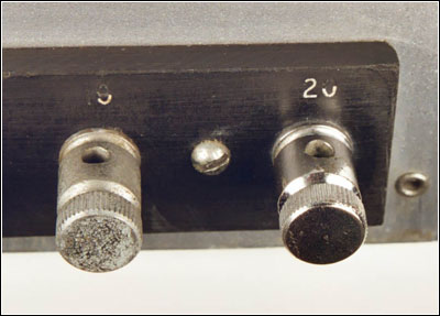
Additional restoration work involved the little details that take so much time. The nickel-plated, brass binding posts on the back were corroded. A buffing first with medium ScotchBrite followed with Brasso shined them up. Both the "as-found" and restored binding posts are shown in Figure 15. The control knobs were dirty and had dust stuck in the fluting. Cleaning with a little water and a toothbrush took care of that.
Most of the white lettering in the engraved escutcheons and the index arrows on the knobs were missing or damaged. The method I used to fill in the engraving was with a "Markal Paint stik®" marker. A paint stick is a large crayon shaped stick of solid paint. You use it just like a crayon and the paint hardens in about 12 hours.
As you would expect, when you first use the stick there is a hard shell formed over the surface. You must scrape off the shell and expose the unhardened paint below. I took the stick and rubbed the paint into the surface of the escutcheons in a small circular motion until all of engraving was filled. I took a paper towel and just wiped off the excess leaving the paint in the engraving. Very deep engraving may require two or more coats to completely fill in. When I was done, I wrapped the paint stick tightly in aluminum foil for storage to prevent it from drying out.
This method works far better and takes much less effort than dabbing on liquid paint and trying to wipe it off. The Paint stik® part #80220 is made by LA-CO Industries in Elk Grove Village, Illinois, and can be purchased from McMaster-Carr, stock #1660T21 in boxes of 12 each for less than a dollar per stick.
After the panel treatments and escutcheon work, I reassembled the panels, controls and knobs.
Electrical Restoration
Along with the cosmetic restoration, I worked on the electrical restoration. The first problem was to create an accurate detailed schematic diagram of the circuit. I had the old Type UX-201A version of the schematic for reference, but it was not close enough to use. I started going through the circuit line by line and drawing up the schematic bit by bit...
Replacing Bad Wiring
The connections to the grid caps on the tubes were made with a blue rubber-insulated wire. The rubber was as hard and brittle as glass. I don't know if this wire was factory original or not, but I suspect that it was because there were some other lengths of this same wire below the chassis in places where it would never have been necessary to replace it. As far as I know, rubber-insulated wire like this is no longer available, so I had to improvise.
There is silicone rubber-insulated wire available that is exactly the same size, appearance, and feel as the old stuff. It is possible to get it in colors on special order but not in the small quantities I use. What I do is use a common white colored wire and dye it.
Figure 13. Back-up plates were added to repair stripped threads.After some experimentation, I discovered that white silicone-insulated wire will accept ordinary Rit fabric dye. The dye penetrates all the way through the insulation. I took measurements of how much wire was required to replace all four grid leads. I cut a sufficient length of silicone wire, plus a little extra. I mixed up some of the powdered dye with hot water in a small container and put the wire in the dye. After a few minutes, I removed the wire, and I had a beautiful blue rubber-insulated wire that was just about the same color as the wire in the radio. I have used this method to replace rubber-insulated wire in 1940s radios with good results.
Figure 15. This before and after photograph shows a cleaned and polished binding post on the right and a corroded post on the left.Switch Repair
Another problem I found was the power switch, shown in Figures 18 and 19 (see print version). Like most battery sets, the power switch controlled only the filament current. The switch was intermittent and had a high resistance. Looking the switch over, I found two plugged holes in the back and screw threads coming out of the opposite side in the front. I dug out some hard wax and found the two screw heads. Removing the screws allowed me to disassemble the switch for cleaning. I cleaned up the contacts and the switch worked fine on reassembly...
Testing
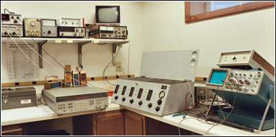
After all of the cosmetic and most of the electrical restorations were done, it was time to try it out with power. My test bench with the Phantom type 9 is shown in Figure 20. The first step was to see if the RF section would work. I connected bench power supplies to the set for filament, screen and RF plate. I turned on the power in sequence of plate, screen and finally the filament. The last RF tube did not light, but wiggling it a little in the socket fixed that. I used the front panel meter to adjust the RF filaments to roughly the nominal 3.3 volts. Immediately the set oscillated, which did not surprise me.
The power supply bypassing was not the greatest and the supplies were bypassed to ground-wire busses instead of the chassis. This almost guarantees problems with ground inductance. Oh well, that's better than smoke, and it does prove that the RF section has enough gain to oscillate.
I disconnected the third and fourth RF amplifier tubes and that stopped the oscillation. To make a measurement of the tuning range I connected an RF signal generator to the antenna input and an oscilloscope to the grid cap connection of the third RF tube. I set the tuning for all of the RF stages to one end of the range and adjusted the RF signal frequency until I saw it come through to the 'scope. I ran the radio tuning to the other extreme and repeated the process. I was pleased to find that it tuned from 525 KHz to 1550 KHz.
Up to this point I had not put the bottom cover back on because I needed to make under chassis measurements. Replacing the bottom cover cured much of the oscillation, but there was still a tendency to take off.
As I was making measurements I saw some modulation on an RF signal at the detector grid. I just couldn't resist the temptation to get some kind of reception. I temporarily connected up a 1N914B diode in place of the detector tube and fed it into an audio amplifier I use for testing. Out came a local Chicago radio station, and it didn't sound too bad. Tuning was a real trial, but I could get a few stations on a short piece of wire for an antenna.
I removed the diode and put in a Type UX-200A tube in the detector socket. When I applied power the UX-200A was working about as well as the diode. I tried a few different resistor values to see if there was any improvement. Changing the grid leak resistance had little to no effect on performance, so I left it at the databook suggested value of 2.5 megohms. The detector seemed to get better gain as I increased the value of the plate resistor, so I ended up changing that from an initial value of 20 K up to 100 K. Next was the audio preamp/driver section.
Audio Preamp Driver Section
For the audio section I picked out several used Type UX-201A tubes from my stock in the old style balloon envelopes. I tested them on a Tektronix 577 curve tracer and selected two that reasonably matched the typical curves published in the RCA HB3 tube data manual. Tube testers are fine for service work and culling duds, but for real design work, nothing can take the place of actual plate curves. I wanted a pair of UX-201As that closely resembled the published curves so that when I did the circuit testing I knew I was going to get results consistent with typical tubes and not troubles with out-of-tolerance samples.
I temporarily pushed some half-watt carbon composition resistors into the resistor clips for testing and attached the additional power supplies required for the audio section. I had audio coming through all the way to the plate of the audio driver tube.
Although the Type UX-201A driver tube was not capable of providing much power, I attached an 8-ohm speaker to the plate of the driver tube through a transformer. The audio was weak, but I could hear my radio station through the speaker. Unloaded, there was about 80 volts peak-to-peak of undistorted audio on the driver plate, plenty to drive the grids of the audio output tubes to full power.
Figure 20. The test bench and the equipment used to fire up and test the Phantom Type 9.I experimented a little with resistor values and supply voltages in the audio section. There was no improvement in either the performance or operating characteristics with anything I changed from the initial values, so I left them as I had calculated. At this point everything was working except the push-pull audio output.
To get the audio output functioning I used a pair of Type UX-245 tubes instead of the factory specified Types UX-210 or UX-250. The Type UX-245 was not released until March of 1928, so it was not used in this radio; however, I had a good reason to use it. Both the UX-210 and the UX-250 are very expensive tubes to buy now. I did not have any of these in stock, but I do have plenty of UX-245s. The Type UX-245 is very similar to the UX-250 for most specifications, except for a 2.5-volt filament and lower plate dissipation rating.
My next measurement was for sensitivity and selectivity. I have some classic high quality Hewlett-Packard test instruments that I use for these measurements. I connected a calibrated RF signal generator to the antenna input and an oscilloscope to the detector grid connection to see what I could find out. Rather than use the push-pull audio output, I reconnected the test audio amplifier to the plate of the first audio tube to get an audible indication of the performance along with the oscilloscope display.
I was able to get a measurable signal at the detector grid, and I could still hear 400 Hz modulation with as little as 10 microvolts of RF. For comparison, I checked a 1939 Emerson "All American Five" AC/DC table radio, and I could hear signals down to about 30 microvolts. Getting that kind of sensitivity on the Phantom was not easy.
Although the Phantom is capable of that kind of sensitivity, it was only possible with the adjustments all perfectly optimized. The RF amplifier tube filaments had to be adjusted so that the RF was on the verge of oscillation. Probably a certain amount of regeneration was going on. The radio has a lot of gain but most of it is wasted in oscillation, if you try to use it.
I went on to see what the selectivity was. I used a sweep generator and set the center frequency to 1000 KHz fixed, and then I tuned the radio for best signal strength at the detector. When the radio was tuned, I set the sweep range from 900 KHz to 1100 KHz. Using the scope and a calibrated marker I was able to determine that the 20db bandwidth was about ±15 KHz. Checking my reference AC/DC table radio, it measured ±8 KHz...
Impressions
Finally, the project was complete! Now I could step back, admire my work and take the photograph of my restored Golden-Leutz Phantom Type 9, shown in Figure 22.
I never had the opportunity to operate one of these old sets, so the possibility of restoration and actually getting one working was doubly compelling. It certainly is not anything like a modern set where you turn one knob and the music comes out. There are five adjustments for tuning, three more for gain and optimizing the performance.
Tuning to a particular frequency is difficult mostly because there is no dial marking that tells you in kilohertz or meters what the wavelength is. The zero to 100 log scale can be used for that if you have a chart that cross references the log numbers and frequencies. In the old days this would have been done entirely by trial and error. Using modern test equipment, I can produce any desired calibrated reference frequency with the RF signal generator and tune the radio until I find it; then, I can record the dial setting.
Tuning for best performance is another trial and error. You have to set the 4-ganged RF stages to a particular frequency and then follow with the 1st RF stage tuner. If you are lucky enough to be receiving something, you rock the ganged tuners and the single tuner back and forth for the best signal and then try the three fine tuning controls to see if that helps.
While this is going on, the RF stages are likely to take off and oscillate. If this happens, you run the RF filaments down until the oscillation just stops. You can usually set the detector filament to some convenient voltage that worked before and leave it, but not always. Sometimes the reception will be noisy and adjusting the detector up or down will clean it up. After all that, you can adjust the volume control. Changing stations you get to start over and adjust everything again.
Connecting up the set to a long wire antenna, I was able to tune in quite a few stations. The sound quality was quite good probably due to the wide bandwidth.
There was quite a bit of knob twisting involved. Without automatic volume control the settings had to be adjusted often to keep the volume at a comfortable level. Adjustment of the RF gain could be critical. On strong stations, it was not a problem, but for weak ones, you needed to squeeze out every bit of gain you could without the set's breaking into oscillation. Just before it oscillated, there was a very sensitive spot where functionally the set was probably more regenerative than TRF. I don't know if the manufacturer intended this or not. The set certainly had plenty of gain, but mostly you were not able to use it because of the unstable design breaking into oscillation.
One thing the experience taught me was to have a lot of respect for the early pioneers who used this type of equipment and made it work for them. By comparison I have a little table model Zenith 705 built in 1933. It was made only five years later than the Phantom, but it is far easier to use and performs far better overall.
The 705 is comparable in performance to any of the typical All American Five sets made over several decades. Technology advanced rapidly and the Phantom was quickly left behind. I feel lucky though to have been able to restore the set to operation and get a taste of what it was like to own and operate a radio on the front edge of technology in 1928.
Figure 22. The completed project!References:
Bintliff, Ray. "Golden-Leutz and the Universal Trans-Oceanic." Antique Radio Classified, Carlisle, Mass., June 2000.
Cunningham Radio Tubes Bulletin, Type CX-322 Tube, Screen Grid Amplifier, n.d.
Cunningham Radio Tubes Engineering Bulletin, Power Amplifier CX-345, March 1, 1929
Gernsback, Hugo. Official Radio Service Manual. Gernsback Publications, 1930, p. 338.
Kitchel, Robert G. "Leutz Universal Trans-Oceanic Type L-6 One-of-a-Kind Console." Antique Radio Classified. Carlisle, Mass., June 2000.
Radio News, July 1927, p. 63; August 1927, p. 99; October 1927, p. 308; May 1928, p. 1,267; June 1928, p. 1,363; July 1928, p. 96; October 1928, p.363; December 1928, p. 521; January 1929, p. 693.
RCA HB-3 Tube Data Manual, data page type 00A, July 1, 1935 and October 31, 1933.
RCA HB-3 Tube Data Manual, data page Type 01A, May 1, 1935 and November 3, 1933.
RCA HB-3 Tube Data Manual, data page type 10 3 Tube Data Manual, data page type 22, August 30, 1935 and August 27, 1935.
RCA HB-3 Tube Data Manual, data page type 45, April 20, 1938 and November 17, 1932
RCA HB-3 Tube Data Manual, data page type 50, July 1, 1935 and September 13, 1935
Rider, John, F. Perpetual Trouleshooters Manual, Volume 1.
Tyne, Gerald F.J. Saga of the Vacuum Tube. Tempe, AZ: Antique Electronic Supply, 1977, pp. 318, 321, 322.
(Daniel Schoo, 526 Colonial Dr., DeKalb, IL 60115)
Daniel Schoo, a frequent contributor to A.R.C., is an electronics design engineer with a lifetime interest in antique technology, especially radio and television equipment. In addition to his collection of 1930s and 1940s radios and video cassette recorders, he has a large collection of vintage vacuum tubes, neon lamps, and tube data books.
| [Free Sample] [Books, etc., For Sale] [Subscribe to A.R.C./Renew] [Classified Ads] [Auction Prices] [Event Calendar] [Links] [Home] [Issue Archives] [Book Reviews] [Subscription Information] [A.R.C. FAQ] URL = http://www.antiqueradio.com/Oct07_Schoo_Golden.html Copyright © 1996-2007 by John V. Terrey - For personal use only. Last revised: September 27, 2007. For Customer Assistance please contact ARC@antiqueradio.com or call (866) 371-0512 toll free Pages designed/maintained by Wayward Fluffy Publications
Antique Radio Classified |