
Of Old Radios And Related Items--Published Monthly
The Riga B417
An Internet-Assisted Restoration ProjectBY JERRY WIELAND
WEB EDITION
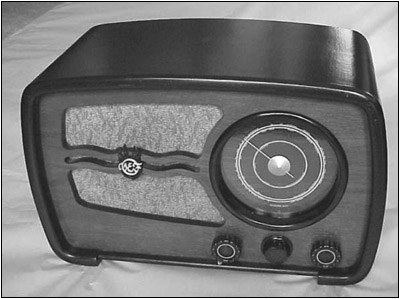
In the following article, Jerry Wieland reveals yet another way in which the Internet can bring collectors together, not just locally, but internationally. Using the A.R.C. Internet Web site link to foreign references and e-mail, Jerry connected with a Russian and a Swedish collector about his Riga B417 -- a success story follows. (Editor)When I first saw the large table radio shown in Figure 1 in a Wisconsin antique shop, it struck me as having a foreign appearance. When I picked it up and saw a cable with crocodile clips plus a line cord with a European plug, I was curious. Was it battery or AC? It rattled ominously, a knob was missing, but the wooden cabinet was in good shape. The price was right, so I bought it.
Days later, a fellow collector saw the name Riga on the rear cover and commented that Riga was a Russian port city. Using the A.R.C. Internet site foreign references, I found a link to a Russian collector's site displaying a radio with a very similar cabinet along with a schematic.
Comparing the tube location chart on the back of my radio to the schematic on his showed the two to be different. His is a 6-tube AC set with 6-volt filaments, whereas mine has a 2-volt battery cable, which I assumed to be the filament supply. The 4 octal tubes used in mine, all of which were missing, had numbers I could not cross reference: DCH21, DF22, DBC21, DLL21.
Figure 1. The Riga Model B417.
The E-Mail SearchAn e-mail to the owner of the Russian site evoked a response that said my set was made in Latvia by the Riga Radio Works before the Soviet takeover in 1940. From 1941 to 1945, the Germans occupied Latvia. After the war, the Soviets gained control. I assume my radio was made in the early 1940s. The Russian collector could not give me any information on the tubes since he collects only Soviet era radios which do not use tubes with low voltage filaments. I downloaded all his Riga schematics hoping that some of the circuitry might be similar to mine.
I also found a Swedish Web site that lists a similar Riga model, but again the tubes didn't match. An e-mail brought the response that my tubes could not be identified. To help find substitutes, the Swedish collector scanned many pages of a 1940s Swedish tube manual and e-mailed them to me. He also provided a page of tube terms he had translated from Swedish to English!
Assessment of the Set
After reviewing all the documentation, I returned to the radio. A closer examination of my B417 revealed a number of problems. The speaker had detached from the front panel ripping away the audio output transformer secondary wires. This explained the rattling. The output transformer has three primary terminals, but only one was connected. Three chassis wires were lying loose. A resistance check of the transformer showed the primary to be open. This transformer was history.
The AC line cord terminated in a separate chassis that is rather crudely built. As Figure 2 shows (see print version), it has a large, probably selenium rectifier and a ripple filter. The capacitors in the output filter were open. A toggle switch marked 110/220 volts varied resistors in series with the load. The output wires to the radio chassis were marked 90 volts and 0 volts with crimp-on metal tags. I believe this power supply was an after-market addition to eliminate the plate supply battery. However, a 2-volt battery was still required for the filament supply resulting in a rather odd power system. I removed the 90-volt supply and concentrated on the main chassis.
The large circular dial is impressive in appearance. However, the pointer did not turn. I found that the pulley was loose on the tuning capacitor shaft and the cables had excessive slack. The pulley supports two cables. One wraps around the tuning shaft and the other around the dial pointer shaft. The tuning shaft can be pushed in to activate a leaf switch which supplies power to the dial lamps. This feature is usually found on battery sets to conserve current.
After making a dial stringing diagram, I removed the dial which exposed the pulley. Rather crudely cast from pot metal, the tuning pulley was in poor condition; it was both cracked and deformed. Small projections for tension spring anchoring had broken off leaving the springs loose. One slot was so deformed that I could not pull the cable through it. Probably another item for the garbage can. I put this aside to concentrate on the circuitry.
Restoration and Modification
Tracing some of the circuits proved that the B417 is similar to an M557 schematic obtained from the Russian Web site. Although the M557 has 6 tubes, one is a tuning eye and the other a rectifier. If I don't count those two, the remaining 4 tubes are similar in function to the tubes in my B417. Both radios have 3 bands -- long, medium, and shortwave. Now I needed to find tubes. Should I convert the set to 6-volt tubes or look for 1-volt substitutes?
In my collection, I have a Motorola portable from the mid-1940s that uses octal tubes with low voltage filaments. I decided to check these tubes against the M557 schematic. The configuration was similar enough to make me decide to try them in the Riga.
I modified one stage at a time starting with the mixer/oscillator, followed by the IF amp, detector, and audio amp. The tube sockets required rewiring since the filament pin-outs of the substitute tubes were different from those of the original tubes. The plates, grids, and cathodes were OK as is.
I used an oscilloscope and signal generator to make sure each stage was operating before proceeding to the next. With this approach I was able to get the AM band operational. It was not as difficult as expected. For power, a multiple output DC supply provided the filament and a 90-volt plate voltage. A junk box audio output transformer and some speaker cone patching completed the operational restoration, at least on the AM band.
From the original transformer configuration, I believe the audio output tube should be a dual triode operating in push-pull. This is what the radio on the Swedish site uses. My current substitute is a single triode, so I did not use a push-pull output transformer. I will try that configuration when I find a suitable dual triode.
Next, I tried my hand at RF and IF alignment. Ferrite slugs protrude through the side of the IF shield cans and have a 5/32 hex head. The antenna coupling coils also have similar slugs but are recessed in the chassis. My socket wrench was too large for the chassis access hole. I had to use a nut driver to tune these which proved to be tricky because the metal shaft detuned the coils. After some tweaking, the AM band was more sensitive. A few stations could be heard on the shortwave band also. On the negative side, the local oscillator dies at the lower shortwave frequencies, and sensitivity on the long-wave band is not very good.
Since the electrical restoration was progressing, I decided to make some progress on the dial and bandswitch. The stop was missing on the bandswitch allowing it to rotate 360 degrees, which bent some of the contacts. I was able to straighten the bent contacts with needle nose pliers. Since it would require extensive disassembly, I did not want to remove the bandswitch from the chassis to investigate the stop problem.
Instead, I fashioned a stop on the chassis from a piece of sheet metal bent to make contact with the collar of the bandswitch indicator. This collar has two set screws which now act as bandswitch stops when they hit the bracket. A short cord attached to this collar operates a tricolored disk that indicates which band is selected through an opening in the tuning dial face. The disk colors match the frequency band colors on the dial face.
The dial mechanism was more difficult to repair. The cast pulley was not salvageable. For a replacement, I consulted my junk boxes. A plastic insert from a lawn table was just the right diameter. To attach it to the tuning capacitor shaft, I used a collar from an old tuning pulley.
After supergluing the collar to the plastic insert, I inserted three small screws for reinforcement. More screws were then added as anchors for the dial cords. Stringing these cords was very difficult because the tuning dial assembly covers the pulley. Once the stringing was accomplished, the dial worked well. All that remained were two dial lamp replacements. An easy job, I thought. However, the two screw base bulbs were glued into their sockets -- with great glue, to say the least. I finally mangled the bulbs with the needle-nose pliers and removed the pieces. The sockets survived to accept 2.5-volt replacement bulbs.
After I had touched up cabinet scratches and added a substitute knob, the radio looked presentable, as shown in the two chassis views in Figures 3 and 4 (see print version). I will continue my search for more suitable tubes, a knob, and a schematic. The set's performance still needs improvement. This is one of those projects that could last for years. However, I would not have gotten this far without the Internet. It proved to be a useful high-tech tool for restoring a rather low-tech radio.
Acknowledgements:Special thanks to the following collectors whose Web sites (see URLs listed below) and personal assistance helped me with this restoration project:
Vitaly Brousnikinhttp://home.onego.ru/~vitalybr/foy.htm
Per-Henrik Fogelstromhttp://hem1.passagen.se/radiola/eradio.htm
(Jerry Wieland, 780 Charleston Ln., Hoffman Estates, IL 60195)Jerry Wieland is an electrical engineer working in cellular phone development at Motorola. His interest in old radios began at age 12 when he started listening to shortwave broadcasts on a 1930s Silvertone console.
A.R.C. Web Site Valuable Resource
BY DOROTHY SCHECTER In this new world of dissolving international barriers, A.R.C.'s Internet Web site is proving to be a valuable resource. As Jerry Wieland's article points out, with a click of your mouse, you can access links to radio-related information round the world via our Web site. Unlike many links which are reciprocal -- that is, the site requires that you reciprocate with a listing on your site -- A.R.C. will list any appropriate radio-related site without restrictions.
Of course, such a partnership of reciprocity is desirable, but we do not require it. As an example, we have 35 sites listed under the "Non-U.S. sites" category alone. Thus, Jerry was able to get information from a Russian site, and, indirectly, from a Swedish site that is still under construction. We're pleased to note that A.R.C., in turn, is listed on the Russian site, and, no doubt, we will connect with the Swedish site when it is ready.
The A.R.C. Web site is a direct route to information that in a more general search on the Web would take you a great deal of time. We serve as a clearing house for what would otherwise be a jumble of responses to your general search. We seek out all related sites, even those of competitors.
If you haven't already taken advantage of our Web site as a resource, we urge you bring up the A.R.C. home page at www.antiqueradio.com. Then click on "Links," and browse through the more than 200 links offered. Tubes, grille cloth, parts, Catalin repair -- almost anything you can name is there.
Even more important than the basic information available is the human connection. You will find, as Jerry Wieland did, many, many people out there able and willing to help with a particular radio-related problem. So, bring up that A.R.C. home page and click away!
(Dorothy Schecter, c/o A.R.C., P.O. Box 2, Carlisle, MA 01741)
| [Free Sample] [Books, etc., For Sale] [Subscribe to A.R.C./Renew] [Classified Ads] [Auction Prices] [Event Calendar] [Links] [Home] [Issue Archives] [Book Reviews] [Subscription Information] [A.R.C. FAQ] URL = http://www.antiqueradio.com/Riga_B417.html Copyright © 1996-2000 by John V. Terrey - For personal use only. Last revised: June 1, 2000. For Customer Assistance please contact ARC@antiqueradio.com or call (978) 371-0512 Pages designed/maintained by Wayward Fluffy Publications
Antique Radio Classified |