VOLUME 16 SEPTEMBER 1999 NUMBER 9
VOLUME 16 SEPTEMBER 1999 NUMBER 9
The Atwater Kent Radiodyne
WEB EDITION
The Atwater Kent feature story in the May 1999 issue of A.R.C. has sparked more Atwater Kent interest. We're glad to have the Radiodyne brought to our attention, as it marked an interesting milestone in Atwater Kent history. (Editor)
BY RAY THOMPSON AND DAVE GONSHOR
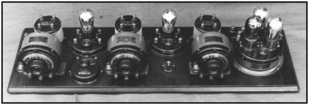
The Radiodyne shown in Figures 1 and 2, also known as "Part No. 4340," was the first Atwater Kent radio to use a tuned radio frequency (TRF) -- a design consisting of three individually tuned stages. It was called the "Wonder Set" by distributors because its three tuned stages made the set very selective compared to earlier designs.
This greater selectivity was a much needed improvement in radio receivers. Prior to September 1923, all radio stations time-shared one of two assigned frequencies. Thus, broad tuning was acceptable in receivers of that period. With the assignment of additional frequencies, improved selectivity was needed to prevent interference from radio stations operating on adjacent frequencies. Consequently, selectivity had become an important feature of radio performance.
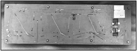
In addition, the Radiodyne was known for its remarkable wiring arrangement. There are no crossed wires under the board. Figure 3 shows the underboard wiring used on the Radiodyne sets.
Soon after A. Atwater Kent had marketed the Radiodyne, he discovered that another company, Western Coil Co. of Racine Wisconsin, had already laid claim to the Radiodyne name. He was forced to change the name quickly to the Model 10, and only a small number of Radiodynes were actually made. Consequently, it is the most desirable of the Model 10s to collect, and the selling price reflects this rarity. Unfortunately, many sets claimed to be Radiodynes have either been modified in some way, or they were not Radiodynes in the first place.
Distinguishing Features
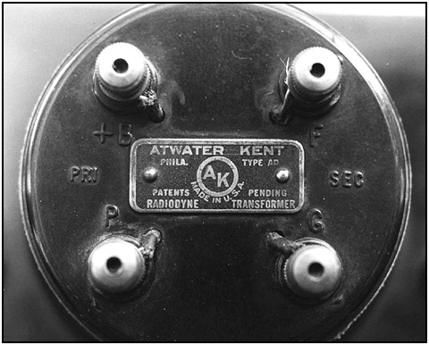
The Radiodyne has many distinguishing features. The primary one is that the metal tags on the Type AD RF coil are labelled "Radiodyne" (not Model 10). One of these brass tags on a Radiodyne RF coil can be seen in Figure 4.
In addition, two paper tags are glued, not tacked, to the bottom of the board. A warranty tag has the board serial number stamped on it; the other tag has instructions about using the new 1/4-ampere filament tubes. Figure 5 (see print version) shows both paper tags under the Radiodyne board. There also may be a larger tag glued, not tacked, to the center of the board identifying the Radiodyne as a No. 4340 set.
In a Radiodyne, the 3-tube TA unit and the tuning condenser cans are painted green. Binding posts are used throughout -- on the tuning condensers, TA unit, RF coils, potentiometer and 1-tube "islands" -- as Atwater Kent had been selling these separately for experimenters to build its own sets prior to the introduction of the Radiodyne. Binding posts are also used to connect to the batteries and the antenna. Figures 6 and 7 (see print version) show the multiple use of brass binding posts on the Radiodyne board components.
The green, 3-tube TA unit has a unique keying pattern for the tubes. Two of the key slots point to the rear of the board; the other slot points to the right. Later breadboard models have one slot pointing left, one right, and one to the rear. This was done to simplify filament wiring. Finally, on very early Radiodynes, aluminum plate switches, left over from the last of the Models 4052 and 4066, were used instead of the familiar Bakelite switches. So, the Radiodyne can have either an aluminum or Bakelite switch.
Figure 1. The Atwater Kent Radiodyne receiver, Part No. 4340.
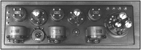
Figure 2. Top view showing the placement of the Atwater Kent breadboard components on the Radiodyne receiver.
Any deviation from these features indicates that either the set is not a Radiodyne, or that parts have been changed. With the exception of the switch, there was no evolution of the parts making up the Radiodyne because of the short production time before the set was changed.Modifications
Any part of an original Radiodyne may have been changed for a variety of reasons. Parts may have broken or been scavenged and been replaced with nonoriginal Radiodyne parts. A common modification to an original board is replacement of the TA unit because of an open winding on one or both of the potted audio transformers. An open winding on an audio transformer was a common failure in the radios of the 1920s. A black or brown, wrinkle-finish TA unit indicates a replacement unit.
The Radiodyne originally came with condenser cans vulnerable to a hand capacitance effect, where the tuning would change as the hand was removed from the dial. To eliminate the hand capacitance effect, all one had to do was to add a jumper wire between the ground terminal and the rotor terminal.
Retail outlets for radios at the time were piano and music stores, department stores, auto dealers and other outfits not versed in radio engineering. It is likely the simple fix to the hand capacitance effect was not understood. Or, perhaps new condenser units were installed simply to charge more money for the repair.
There is no evidence that Atwater Kent authorized any such modification, as Radiodynes were manufactured for only a short time, followed by the identical Model 10 (so identified by the tags on the RF coils) and then quickly by the Model 10 without binding posts on the components. In any event, tuning condensers without binding posts indicate that they have been changed for whatever reason.
Another clue is that the binding post type condensers had to have three holes drilled in the board on the front face of the condenser units. The condensers without binding posts would have two holes in the board towards the rear of the cans, so the existence of holes (plugged or open) on the board in front of the cans is an indication that it is a Radiodyne board. Figure 8 (see print version) shows a front view of a Radiodyne tuning condenser with three binding posts having their wires leading into the board holes.
Figure 3. The wiring underneath the Atwater Kent Radiodyne breadboard receiver. Note that the wires do not cross over each other.
Figure 4. The name "Radiodyne" is clearly shown on the Type AD RF coil.
Certainly these modifications lessen the value of a particular Radiodyne set, but they may not indicate that the set was not originally a Radiodyne. Whatever early Model 10 version you have, it is desirable because of the use of binding post parts and because the history of the Radiodyne is intriguing, as foretold by its early title -- the "Wonder Set."References:
Broadcast Program, "Atwater Kent Radiodyne," n.d.
Williams, Ralph. Radio Age Newsletter, "A. Atwater Kent, the Man, the Manufacturer and his Radios, Parts XI and Xii," n.d.
(Ray Thompson, 7422 Cherry Tree Dr., Fulton, MD 20759. Dave Gonshor 7121 S. Jellison St., Littleton, CO 80128)
Ray Thompson's old radio collecting began in high school, progressed to serious battery set collecting in 1977, and then to specializing in Atwater Kent, RCA and DeForest. Around 1994, he decided to confine his collection to Atwater Kent artifacts. He is an engineer in space research and has worked with the spacecrafts Voyager, Galileo and Cassini, to name a few.
Dave Gonshor, a registered professional electrical engineer, has been collecting radios for approximately five years. He enjoys battery sets and an occasional 1930s tombstone, cathedral or console because of the more interesting electrical restoration they require.