
Of Old Radios And Related Items--Published Monthly
Golden-Leutz and the Universal Trans-Oceanic
BY RAY BINTLIFF, W1RY
WEB EDITION
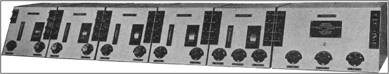
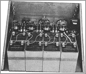
Figure 1. The impressive Universal Trans-Oceanic. Each of the six units is housed in fully shielded cabinets. There are enough controls to satisfy any "knob-twister." This and the other illustrations in this article are taken from the Golden Leutz catalog.
Robert Kitchel's article about the Leutz L-6 piqued John Terrey's curiosity and sent him scurrying to his and the A.R.C. library to look for more on Golden-Leutz, Inc., and, as so often happens, one piece of information led to another. His findings -- the Leutz catalog and other references -- are the basis for this article.Charles Leutz developed an early interest in radio and obtained his Amateur license at the tender age of 14. His early experiences have been well documented elsewhere and will not be repeated here. The references listed at the end of this article are excellent sources of information about Leutz and his companies. However, it should be noted that in 1921 he formed the Experimenters Information Service to sell blueprints and construction data to radio Amateurs and other set builders.
Golden-Leutz, Inc. was created in May 1921 and the Experimenters Information Service became part of the new corporation. Leutz was its president and his partner was Claude Golden. The company was located in the Long Island City section of Queens, a borough of New York City. The name of the company was changed to C. R. Leutz, Inc., in February 1927, and in October 1929, the company relocated to Altoona, Pa.
The company's catalog for the 1927 model year is dated June 1926 and still carries the Golden-Leutz name. The catalog proclaims Golden-Leutz to be "Manufacturers of the Highest Class Radio Apparatus in the World." Several new models were offered in its 1927 line, but the Navy Model Universal Trans-Oceanic receiver, also called the Silver Ghost, is of particular interest here because of its similarity to the radio discovered by Robert Kitchel.
Universal Trans-Oceanic
The Universal Trans-Oceanic, with a price tag of $950, was clearly the company's top-of-the-line set. In its 1927 catalog, Golden-Leutz hailed the radio as "The Most Powerful Broadcast Receiver in the World." Evidently, modesty was not one of the company's strong traits. But such advertising hype was not uncommon during that period.
The radio, shown in Figure 1, is impressive because of its size (6 feet in length) and orderly panel layouts. It is no lightweight, as it weighs in at 140 pounds. In defending the radio's size, the Golden-Leutz catalog states, "The Universal Trans-Oceanic has been designed for universities, broadcasting stations for relay purposes, and true amateur experimenters who want to secure maximum results regardless of the number of tubes and batteries required or the space occupied."
The radio's specifications are equally impressive. By means of plug-in coils, the radio tunes from 3,600 meters to 35 meters, or about 80 kHz to 8 MHz. It is a 4-stage TRF set with a detector and 4 stages of "Distortionless Audio Frequency Amplification."
As Figure 1 shows, the receiver consists of 6 separate units, each housed in individually shielded cabinets. From left to right these units are the 1st RF stage, 2nd RF stage, 3rd RF stage, 4th RF stage, detector stage, and a 4-tube audio amplifier. Binding posts and metal straps are used to make the electrical connections between the units. Each unit contains its own B batteries. The radio's hook-up diagram calls for a 6-volt storage battery as the filament voltage for all units and a cone-type speaker 3 feet in diameter.
Although there are 5 main tuning controls for the 1st RF through the detector stage, these individual controls may be ganged mechanically by means of universal joints to achieve 1-knob tuning. When ganged, the Resonator controls are used to fine tune each stage. When not ganged, each resonator control is set to its mid-position and each stage may be individually tuned for best reception of the desired station.
The 1st RF Stage
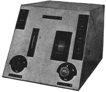
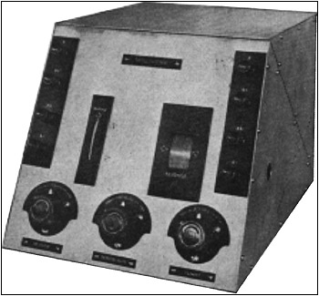
Figure 2 provides an external view of the 1st RF Stage. The binding posts at the top left serve as the antenna and ground connections. The thumb-wheel turns the variable capacitor and the tuning dial at the right. The controls at the bottom of the panel are the antenna coupling switch at the left, and the filament rheostat on the right.
Figure 2. Front panel view of the 1st RF stage with its cover in place. The antenna and ground binding posts are located on the top left corner of the unit. The binding posts on the right make electrical connections to the 2nd RF stage. The thumb-wheel dial, center left, is mechanically linked to the tuning dial, center right, and the variable capacitor. The antenna coupling switch is located at the bottom left, and the filament rheostat to control RF gain is located at the bottom right.
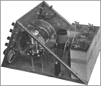
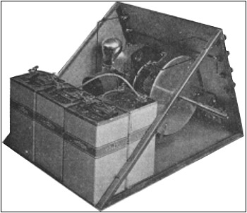
An internal view, Figure 3, shows the components of the 1st RF stage. Note the tube and tube socket on a raised mounting and the transverse-mounted tuning capacitor. The RF coil is in the background and the filament rheostat appears in the lower left corner. The filament rheostat controls RF gain. Two Eveready B batteries are positioned at the rear of the unit. Each of the four RF stages use a single Type UX201-A tube. Plate voltage for the RF stages is 45 to 120 volts.
Figure 3. This internal view of the 1st RF stage shows its sloping front panel and components. The tube is mounted on standoffs to minimize capacitance effects. This unit, like all of the others, contains its own B batteries.
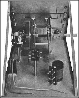
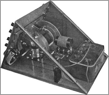
The 2nd RF StageThe 2nd RF stage is similar to the 1st unit. Figure 4 provides another view of the transverse-mounted tuning capacitor as well as a plug-in coil removed from its socket. A vernier tuning capacitor or resonator is visible on the lower right side of the front panel. The B batteries have been removed in this photograph.
The 3rd and 4th RF Stages
These units appear to be identical to the 2nd RF stage. A view of the 3rd RF stage is shown in Figure 5. The large disk on the right side is the thumb-wheel. This metal disk also serves to shield the tuning capacitor. In its catalog, Leutz emphasizes the use of extensive shielding to prevent feedback and oscillation.
The Detector Stage
The detector stage differs from the RF stages in that it uses a Type UX200 tube and a plate voltage in the range of 16 to 22 volts. External and internal views of the unit appear in Figures 6 and 7.
The Audio Amplifier
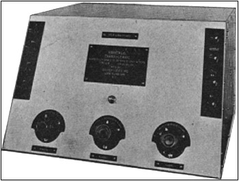
This 4-tube amplifier, shown in Figures 8 and 9, uses one Type UX112 tube in the 1st audio stage and a Type UX201-A in the 2nd and 3rd audio stages. Either a Type UX171 or UX210 is recommended for the audio output stage. The appropriate plate and bias voltages will depend on the type of output tube used. The controls at the bottom of the panel are filament rheostats that control the gain of the AF stages.
Figure 4. This internal view of the 2nd RF stage with batteries removed shows the raised tube and coil sockets. Note the transverse mounted variable capacitor with its shaft extension used to link it to the adjoining units.
Figure 5. Golden-Leutz placed great importance on the use of extensive shielding. This view of the 3rd RF stage shows the metal thumb-wheel that also serves as a shield for the variable capacitor.
Schematics for the CuriousPage 447 of the 1931 edition of John Rider's Trouble Shooter's Manual contains a schematic diagram for the battery-operated Universal Trans-Oceanic. A schematic for the AC-operated version can be found in Rider's Volume I on the Leutz page 1-1.
Some Additional Thoughts
Looking at the schematic for the battery-operated set makes one wonder about the cost of equipping and replenishing the batteries for this radio.
The use of plug-in coils give the radio a wide tuning range, but changing coils in all five tuned circuits must be time consuming.
On the positive side, there is no question that the radio is well shielded, and good selectivity results
Figure 6. This external view of the detector stage shows it to be similar to the 1st and 2nd RF stages, except that it has an added control knob at the bottom center of the panel. The three controls are marked "Resonator", "Detector Plate", and "Filament."
Figure 7. This internal view of the detector stage shows it to be similar to the 2nd and 3rd RF stages except that it uses a smaller battery.
Figure 8. The radio's nameplate is mounted on the front panel of the audio amplifier unit. The controls at the bottom are filament rheostats.
Figure 9. This internal view of the audio amplifier shows its components and the 8 batteries that are required to operate it.
from the 5 stages of tuned RF (4 RF and 1 detector stage). Tracking the 5 stages must have been a challenge for its designer and the resonator controls were his way around the problem.Considering the state of radio design and performance in the mid-1920s, the Universal Trans-Oceanic must have been a powerful radio. Perhaps the Golden-Leutz claim that it was "The Most Powerful Radio in the World" was not an overstatement.
The use of the name Trans-Oceanic is interesting. Who was the first to use it? Leutz or Zenith?
References:
Caperton, John H. "Charles R. Leutz." Madison, Conn.: The Antique Radio Gazette,No. 4, 1977.
Douglas, Alan. Radio Manufacturers of the 1920's, Vol. 2. Vestal, New York: The Vestal Press, 1989.
Golden-Leutz, Inc. Catalog. New York, 1927.
Nelson, Wayne. "The Leutz Story." A.W.A. Monograph No. 7.
(Ray Bintliff, 2 Powder Horn Ln., Acton, MA 01720)
Ray Bintliff holds an Amateur Extra Class license. A retired engineer, he enjoys repairing and restoring pre-1945 radios and test equipment. In addition to Amateur Radio, his interests include electronic equipment design and audio reproduction.
| [Free Sample] [Books, etc., For Sale] [Subscribe to A.R.C./Renew] [Classified Ads] [Auction Prices] [Event Calendar] [Links] [Home] [Issue Archives] [Book Reviews] [Subscription Information] [A.R.C. FAQ] URL = http://www.antiqueradio.com/bintliff_Golden-Leutz.html Copyright © 1996-2000 by John V. Terrey - For personal use only. Last revised: June 1, 2000. For Customer Assistance please contact ARC@antiqueradio.com or call (978) 371-0512 Pages designed/maintained by Wayward Fluffy Publications
Antique Radio Classified |