Of Old Radios And Related Items--Published Monthly
The Colonial "Globe" Radio
BY EDWARD KRAWCZYK
WEB EDITION
Novelty radios are always eye-catchers, but the "Globe" radio really stands out. Because of its construction, repair or restoration of this radio is likely to be more challenging than that of radios housed in conventional cabinets. But if you are ready to take on the "world," Edward Krawczyk has some handy hints for you. (Editor)
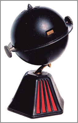
Even among novelty radios, the Colonial Model 700 "Globe," circa 1933, is a standout. The unique radio, shown in Figure 1, is a 5-tube AC/DC set, although Colonial also produced an AC-only model. The AC/DC version uses the following tube types: a 6A7 oscillator/mixer, a 78 IF amplifier, a 75 detector/AVC, a 43 audio output and a 25Z5 rectifier. The tube filaments are wired in series and a resistance line cord is used to drop the line voltage to the required filament voltage.
If your first reaction is, "How do I get this thing apart?" relax. Rider Volume IV provides complete instructions for removing the two halves of the globe and getting to the chassis.
Resistance Line Cord
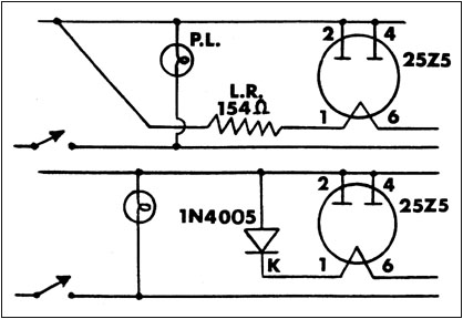
Since the radio uses a resistance line cord, you may be concerned that the line cord is bad and ask yourself "Where do I get a replacement?" Again, don't worry. I installed a new 2-wire line cord and, as shown in Figure 2, I substituted a silicon diode, Type 1N4005, for the resistance element in the old line cord. Because the diode conducts only on the positive half-cycle, it produces about 60 VAC, which is close enough to the 69 volts required by the filament string.
Figure 1. This Model 700 "Globe" radio by Colonial Radio Corporation, circa 1933, consists of a world globe mounted on a base. The set is also referred to as the "New World" model.
Construction of the Globe Radio
The main chassis assembly is mounted in the globe. This chassis contains the 6A7, 78, 75 and 25Z5 tubes and their associated components. The 43 audio output tube is located in the radio's base along with the output transformer and speaker. Electrical connections between the main chassis and the base-mounted components are made by a cable. Quite likely, you will find the wires in this cable are frayed or broken. In the worst case, the wires may have been cut by someone attempting to repair the radio.
Replacing the Cable
Replacing the wires in this cable can be a tedious process because they must be fed through the gooseneck that mounts the globe to the base. Figure 3 illustrates the technique that I used to simplify the task of pulling the replacement wires through the gooseneck.
Working on one wire at a time, I temporarily soldered each new wire to an old wire. Then pulling on the old wire, I eased each new wire through the gooseneck. As you do this work, it is a good idea to make a sketch of what you have done. Using a different color for each wire is also helpful. The use of stranded wire with plastic insulation is recommended for the new wiring.
Figure 2. These "Before" (top) and "After" (bottom) schematic diagrams show the use of a solid-state rectifier as a resistance line cord substitute.
One of the original wires is shielded, and for a replacement, I use a "mini" mike cable available at Radio Shack. If you have a problem locating the shielded cable, I have a limited supply that I will gladly share.
Other Thoughts
I recommend that all capacitors be replaced while you have access to the chassis. And finally, when you reassemble the radio, be sure to heed the notice that appears in the Rider manual. It states, "The chassis and shafts are above ground potential, making it necessary to insulate the knobs and the equatorial ring from the shafts by means of fibre bushings. Note that the bushing in the knob is closed on one end to prevent the shaft from touching the knob. Be sure these insulating bushings are properly replaced after disassembling the Globe."
The unusual appearance of this radio and its high market value are good reasons to tackle the restoration of a Colonial Globe.
(Edward Krawczyk, 64 Old Chimney Rd., Upper Saddle River, NJ 07458)
Edward Krawczyk has been active in radio repair and restoration since his high school years when he bought and sold kits at a profit. He attended an electronic school and worked at IT Labs in New Jersey as an electronics techician repairing and calibrating test equipment of all types. After leaving the labs, he operated a TV service.
Figure 3. "Parallel" soldering the old and replacement wires facilitates snaking the new wires through the gooseneck.
| [Free Sample] [Books, etc., For Sale] [Subscribe to A.R.C./Renew] [Classified Ads] [Auction Prices] [Event Calendar] [Links] [Home] [Issue Archives] [Book Reviews] [Subscription Information] [A.R.C. FAQ] URL = http://www.antiqueradio.com/colglobe_Sep-00.html Copyright © 1996-2000 by John V. Terrey - For personal use only. Last revised: September 4, 2000. For Customer Assistance please contact ARC@antiqueradio.com or call (978) 371-0512 Pages designed/maintained by Wayward Fluffy Publications
Antique Radio Classified |